
Adjusting timestamps to preserve update timing information for cached data objects

a data object and cache technology, applied in data processing applications, memory adressing/allocation/relocation, instruments, etc., can solve the problems of data not being mirrored directly from a cache, data being fraught with problems, and using a host level cache (i.e. accessible by the host, primary storage subsystem) is fraught with problems

Inactive Publication Date: 2004-02-12
IBM CORP
View PDF11 Cites 135 Cited by
  • Summary
  • Abstract
  • Description
  • Claims
  • Application Information

AI Technical Summary

Benefits of technology

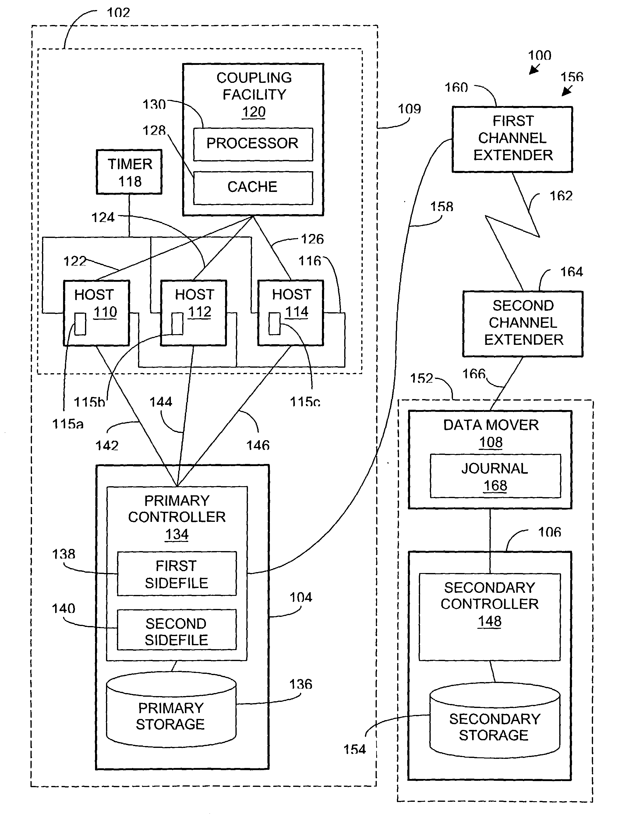
[0015] The system of the present disclosure affords its users with a number of distinct advantages. Chiefly, this system provides performance advantage by quickly storing data objects in a cache. Another advantage is realized by preserving timestamp information indicating when the data objects were updated and written to the cache. The disclosed system facilitates maintaining cached and non-cached data objects in sequence consistent order even if data objects that are dependent on cached data objects, are written to a primary storage before the cached data objects are written to the primary storage. The invention also provides a number of other advantages and benefits, which should be apparent from the following description.

Problems solved by technology

Caches are commonly used within primary and secondary data storage subsystems, but the inventors discovered that using a host level cache (i.e. accessible by the host apart from the primary storage subsystem) is fraught with problems.
Namely, there would be significant problems with maintaining sequence consistent order between data temporarily stored in the cache and other that is written directly to the primary storage, and particularly when that data is dependent on the data stored in the cache.
Consequently, data cannot be mirrored directly from a cache.
Thus, for previously cached data, the time that the data was updated by the application and originally stored in the cache would be lost.
Consequently, because the timestamp associated with the cached data object would not accurately indicate the time the cached data object was updated, the cached data object would not necessarily be maintained in sequence consistent order in primary storage with other data objects that are dependent on the cached data object, and which are written directly to primary storage.
The inventors also found that sequence consistent order also might be lost if there were nothing to guarantee the writing of cached data updates to primary storage by the time that later data updates in primary storage are grouped from sidefiles into consistency groups and sent to secondary storage.
Consequently, the data in the cache would not be maintained in sequence consistent order with other data.
Accordingly, there would be a number of challenges and difficulties to overcome in utilizing a cache with a remote data shadowing system.

Method used


Image

  • Adjusting timestamps to preserve update timing information for cached data objects
  • Adjusting timestamps to preserve update timing information for cached data objects
  • Adjusting timestamps to preserve update timing information for cached data objects

Examples


second example

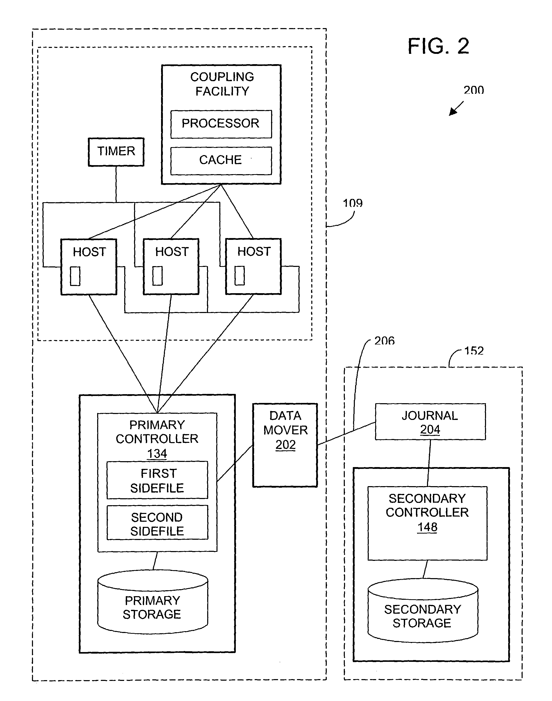
[0043] In an alternative system 200 shown in FIG. 2, the data mover 202 does not include a journal. In FIG. 2, the data mover 202 is located at the primary site 109 and a separate journal 204 is located at the secondary site 152. In this alternative embodiment, the data mover 202 is coupled to the journal 204 by a link 206. The data mover 202 is also coupled to the primary controller 134. In one example, link 206 comprises an extended link as described above. In another embodiment, the link 206 is an ESCON or FICON link, or other suitable link. The journal 204 is coupled to the secondary controller 148. As an alternative, the journal 204 is omitted, and the data mover 202 is coupled directly to the secondary controller 148.

third example

[0044] In another alternative system 300 shown in FIG. 3, the data mover 302 is located at a third site 304. In this alternative embodiment, the data mover 302 is coupled to the primary controller 134 by a link 306 such as an ESCON or FICON link or an extended link. The data mover 302 is coupled to the journal 308 by a link 310 such as an ESCON or FICON link, or an extended link. The journal 308 is coupled to the secondary controller 148. Alternatively, the journal 308 may be located at the third site 304, in the data mover 302, or separate from the data mover 302. Alternatively, there is no journal 308, and the data mover 302 is coupled directly to the secondary controller 148.

fourth example

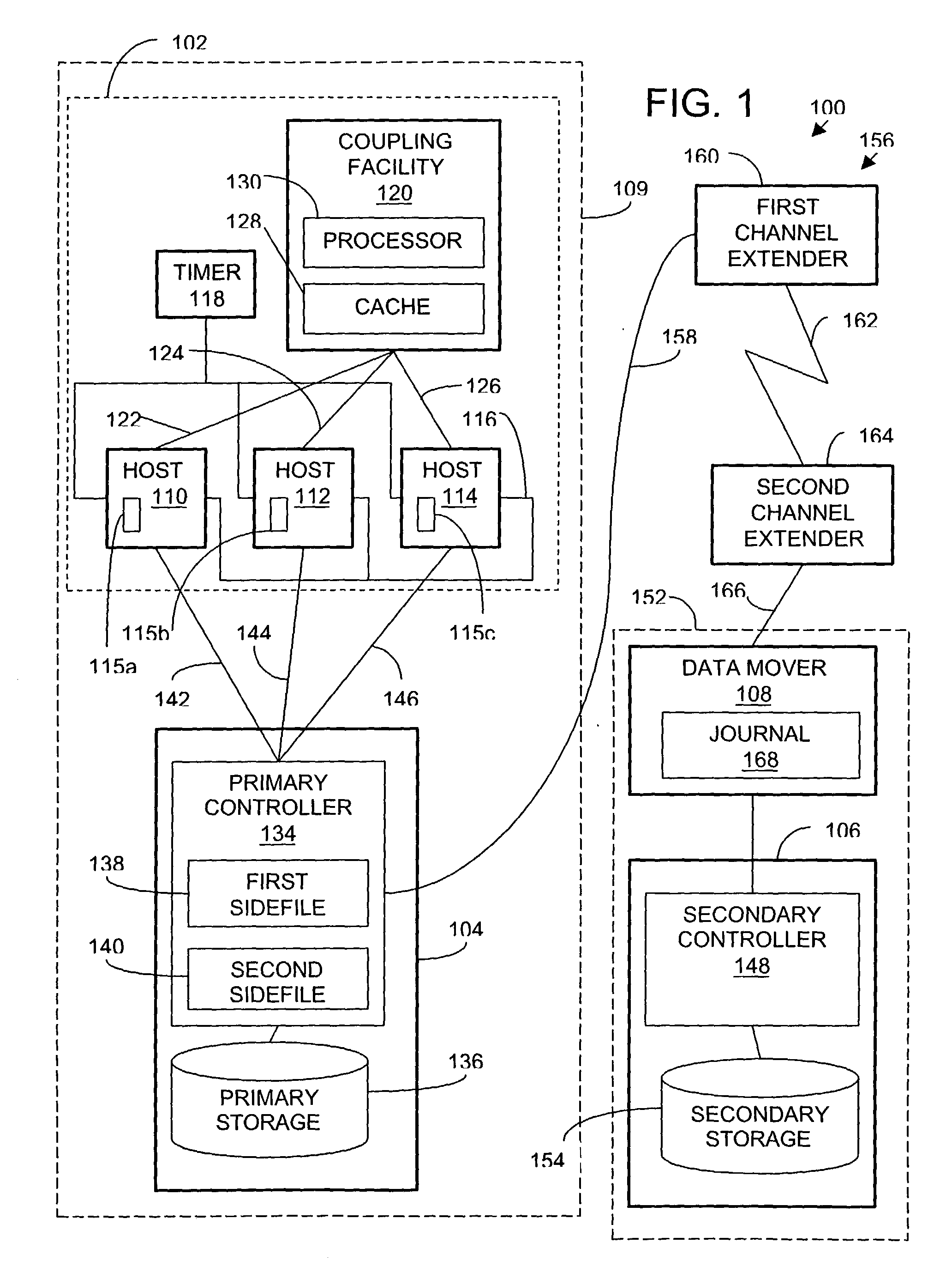
[0045] An alternative example is illustrated by the system 400 in FIG. 4. The system 400 includes a host 402, a cache 404, a primary storage subsystem 406, a secondary storage subsystem 408, and a data mover 410. In contrast to the system 100 in FIG. 1, in the system 400 of FIG. 4 the cache 404 is not part of a coupling facility, there is no timer, and there is only one host 402. Also, in the illustrated example of the system 400, a primary storage controller 412 is coupled to the data mover 410 with an ESCON or FICON link 414. Otherwise, the components, connections, and operation are generally the same in the system 400 as in the system 100. In an alternative embodiment of the system 400, a timer may be coupled to the host 402. Also, in an alternative embodiment, the primary controller 412 may be coupled to the data mover 410 with an extended link, as described above with reference to FIG. 1.

[0046] In the system 400 of FIG. 4, the host 402, the cache 404, and the primary storage su...


PUM


Abstract

In a system including a host, a primary storage subsystem coupled to the host, a cache coupled to the host and separate from the primary storage system, a secondary storage subsystem, and a data mover coupling the primary and secondary storage systems, data is temporarily cached for future storage in the primary storage subsystem so as to preserve timestamp information and maintain data consistency for asynchronously mirroring the data at a secondary subsystem.

Description

[0001] 1. Field of the Invention[0002] The present invention relates to asynchronous data mirroring systems. More particularly, one aspect of the invention concerns a method of temporarily caching data for storage in a primary storage subsystem for asynchronous mirroring at a secondary storage subsystem without sacrificing timestamp information.[0003] 2. Description of Related Art[0004] For many businesses, governments, and other computer users that update and store data at a primary site, it is essential to maintain a backup copy of the data at a secondary site that is physically remote from the primary site. This permits recovering data from the secondary site in the event of an equipment failure or other disaster, for example a fire or explosion, that damages or destroys data at the primary site. Copying data to a remote secondary site as a backup for disaster recovery is referred to as data shadowing, data mirroring, data duplexing, or remote copying. In order to be able to accu...

Claims


Application Information

Patent Timeline
IPC IPC(8): G06F3/06G06F12/00G06F12/08G06F12/16
CPCG06F11/2064G06F11/2074Y10S707/99953G06F12/0866Y10S707/99952G06F11/2076
Inventor GEINER, ROBERT VAUGHNKERN, RONALD MAYNARDMCBRIDE, GREGORY EDWARDMICKA, WILLIAM FRANKNICK, JEFFREY MARKPERRY, LARRY RICHARDPETERSEN, DAVID B.SHACKELFORD, DAVID MICHAELSLONE, HAROLD GLENYUDENFRIEND, HARRY MORRISZOBRE, DOUGLAS M.
Owner IBM CORP
Learn More