Engine lubrication system

a technology of engine lubrication and lubricant, which is applied in the direction of engine lubrication, engine cooling apparatus, filtration separation, etc., can solve the problems of insufficient lubrication, inability to divert a significant proportion of pumped lubricant, and inability to provide adequate lubrication

Inactive Publication Date: 2004-02-19
PIERBURG PUMP TECH UK
View PDF11 Cites 30 Cited by
  • Summary
  • Abstract
  • Description
  • Claims
  • Application Information

AI Technical Summary

Problems solved by technology

However at higher engine speeds, such mechanical pumps tend to pump lubricant in excess of that which is required for lubrication, making them inefficient, and in non-steady conditions, for example when the engine is operating at low speed under heavy load, it is possible that adequate lubrication will not be provided.
However a straight replacement of the conventional mechanically driven pump with an electrically driven pump only overcomes some of the deficiencies of using conve

Method used


Image

  • Engine lubrication system
  • Engine lubrication system

Examples


Embodiment Construction

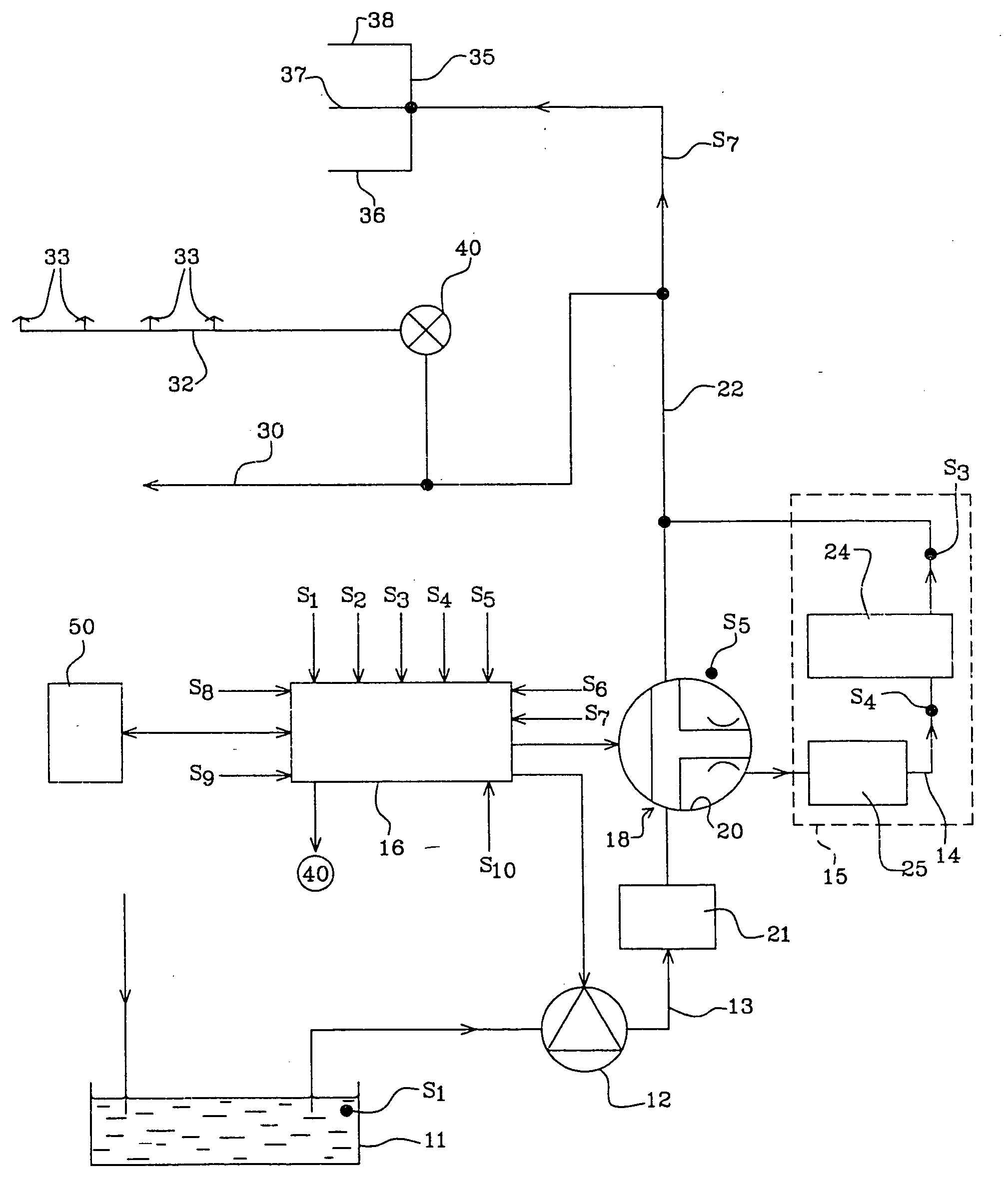
[0034] Referring to FIG. 1 of the drawings there is shown a lubrication system 10 for an engine. The system 10 includes a sump 11 for lubricant, a pump 12 to pump lubricant along a lubricant feed line 13 to various lubrication positions within the engine, and a lubricant conditioner 15.

[0035] The pump 12 is an electrically driven pump, such as a brushless D.C. pump, which is controlled by a system controller 16 which may be a dedicated lubrication system controller as shown, or may be integrated entirely or in part with a general engine management system or into the pump 12 or into a valve, e.g. valve 18 which the controller 16 controls, as desired.

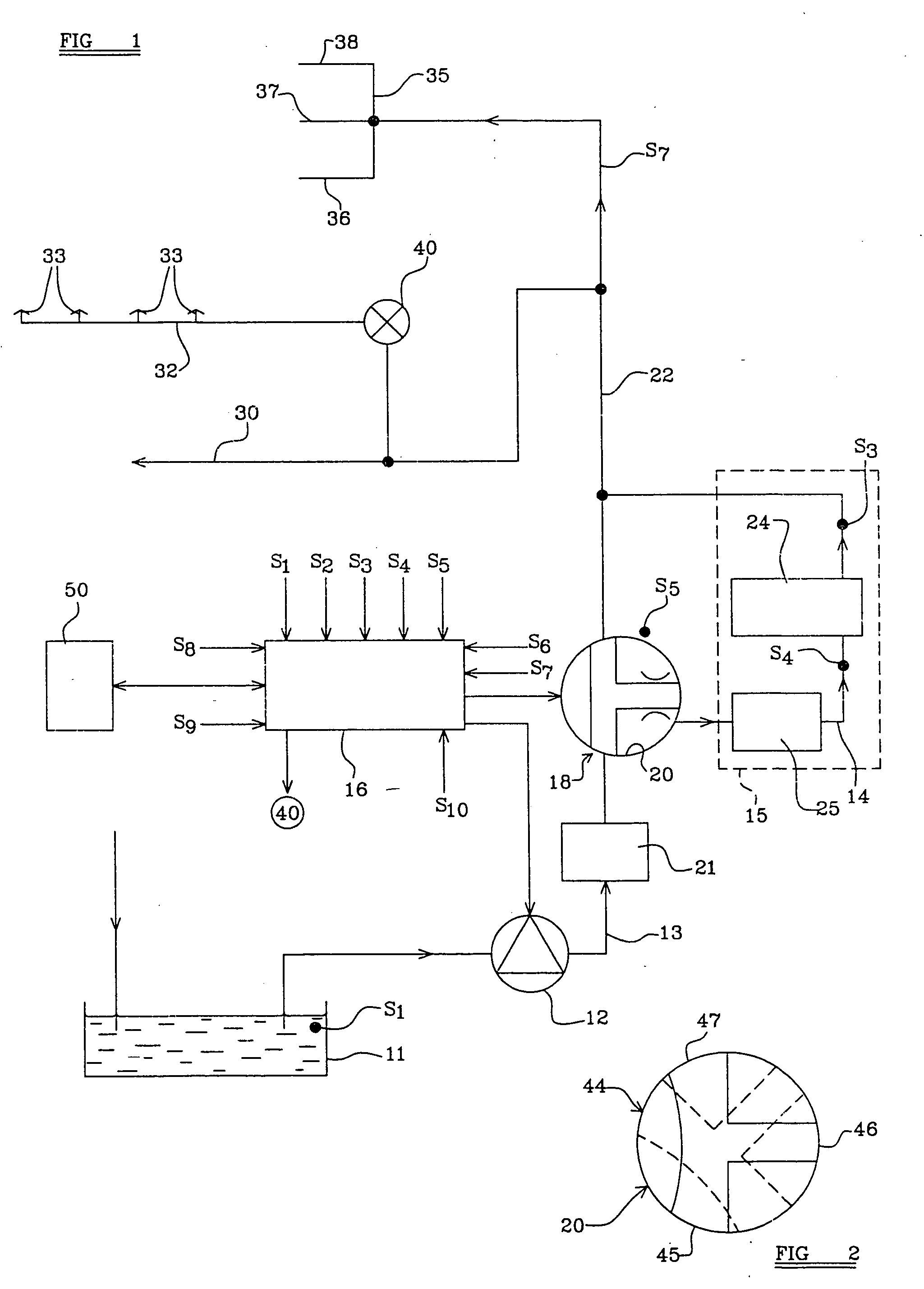
[0036] Within the lubrication feed line 13, there is provided a diverter valve 18 which is an electrically driven valve, which includes a valve member 20 which is described in more detail below with reference to FIG. 2, the rotational position of which may be adjusted under the control of the controller 16 selectively to divert at least a...


PUM

PropertyMeasurementUnit
Temperatureaaaaaaaaaa
Pressureaaaaaaaaaa
Flow rateaaaaaaaaaa

Abstract

A lubrication system for an engine includes a sump for lubricant, a pump to pump lubricant along a lubricant feed line to lubrication positions within the engine, and a lubricant conditioner, and wherein the pump is an electrically driven pump which is controlled by a system controller, there being a diverter valve which is under the control of the controller selectively to divert at least a proportion of the lubricant from the lubricant feed line to the lubricant conditioner.

Description

[0001] This invention relates to an engine lubrication system and to a method of operating such a system.DESCRIPTION OF PRIOR ART[0002] Conventionally engine lubrication systems include a mechanically driven lubrication pump, the output of which is solely dependent upon the engine speed. In steady conditions and at lower engine speeds such mechanical pumps work well and efficiently. However at higher engine speeds, such mechanical pumps tend to pump lubricant in excess of that which is required for lubrication, making them inefficient, and in non-steady conditions, for example when the engine is operating at low speed under heavy load, it is possible that adequate lubrication will not be provided.[0003] Accordingly it has previously been proposed to utilise an electrically driven lubrication pump, the output of which can be varied intelligently to match engine operating conditions. However a straight replacement of the conventional mechanically driven pump with an electrically drive...

Claims


Application Information

Patent Timeline
IPC IPC(8): B01D35/02F01M1/02F01M1/08F01M1/16F01M5/00F01M11/02F01M11/03F01M11/10F01P3/08F16N7/14F16N25/00F16N29/00F16N29/04F16N39/02F16N39/06
CPCF01L9/04F01M1/02F01P3/08F01M5/005F01M2001/0215F01M1/16F01L9/20F16N7/00F16N7/14F16N7/38F16N13/00F16N29/00F16N39/00
Inventor WILLIAMS, DAVID JOHNBLACK, DAVID THOMAS
Owner PIERBURG PUMP TECH UK
Why Eureka
Try Eureka