

Electomagnetic detection apparatus
- Summary
- Abstract
- Description
- Claims
- Application Information
AI Technical Summary
Benefits of technology
Problems solved by technology
Method used
Image

Examples
Embodiment Construction
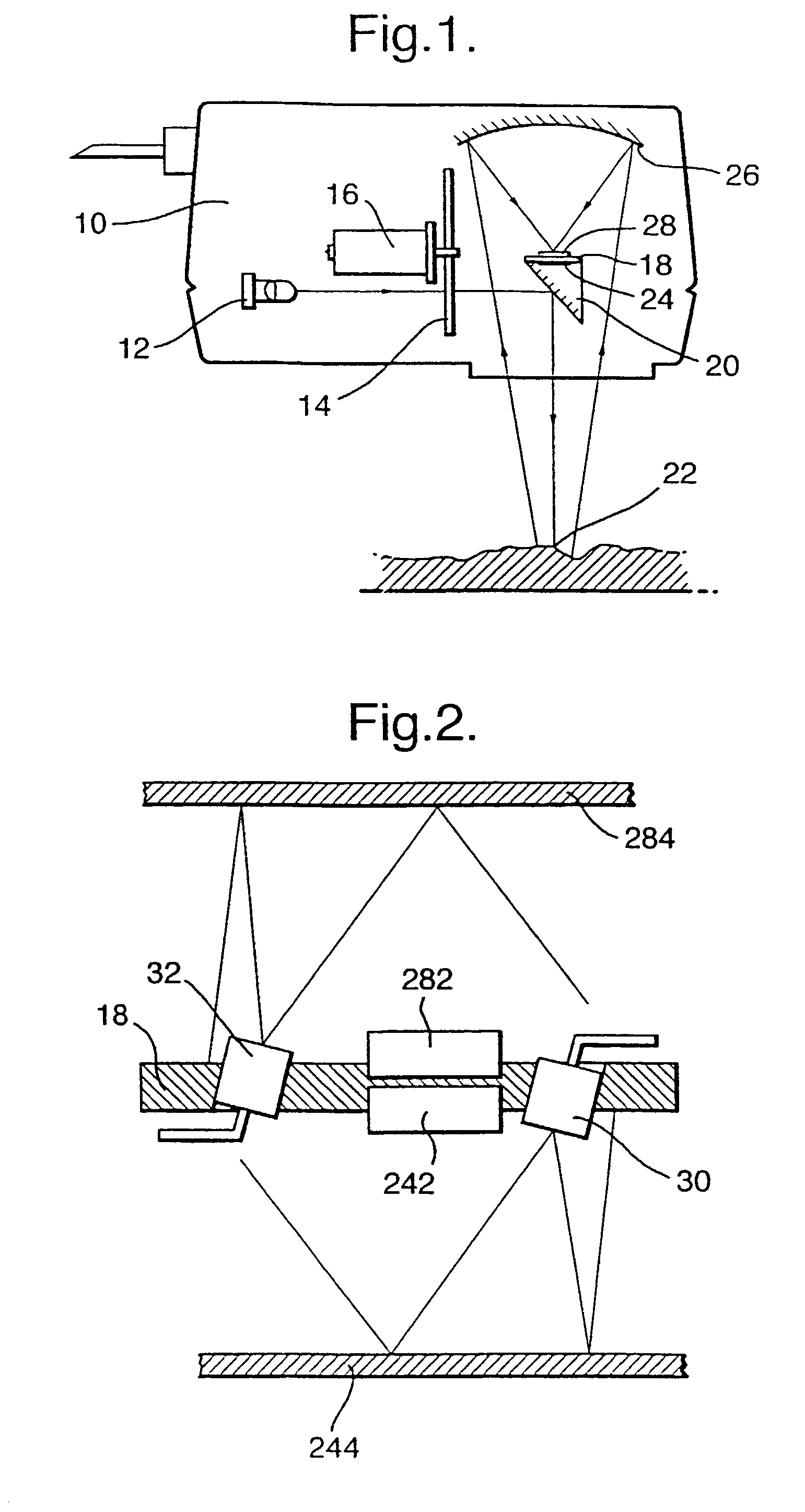
[0033] Referring initially to FIG. 1, this shows the head 10 of a known infrared gauge, for example as described in our published PCT application No. WO98 / 22806. The head 10 contains a lamp 12 providing a source of infrared radiation, and a circular filter wheel 14 driven by a motor 16. The filter wheel 14 carries a series of filters, for example 5 filters, and each filter is designed to pass a different selected emission Wavelength. The light passed by the respective filters is directed towards a detector mounting table 18, as described below.
[0034] The mounting table 18 carries a beam splitter 20 which reflects a portion of the light beam downwardly out of the infrared gauge 10 towards a sample 22. A remaining portion of the infrared light beam striking the beam splitter 20 is refracted within the beam splitter towards a detector assembly 24 including a photo-electric sensor. Meanwhile, the light emitted by the head 10 towards the sample 22 is reflected back from the sample 22 tow...
PUM
 Abstract
Description
Claims
Application Information