
Method and apparatus for transferring control in a computer system with dynamic compilation capability

Inactive Publication Date: 2004-03-04
IBM CORP
View PDF5 Cites 74 Cited by
  • Summary
  • Abstract
  • Description
  • Claims
  • Application Information

AI Technical Summary

Problems solved by technology

Thus, unless high code reuse is present in an application, dynamic compilation cannot improve program execution performance and it may actually deteriorate significantly.
This approach is limited by the design constraints for the switch table.
However, the size (i.e., the number of entries) of CAM structures is inherently limited by the capabilities of the CAM structures, and large numbers of entries lead to slow circuitry which limits processor frequency.
If a CAM structure is not used to provide single cycle table access, the design incurs a significant CPI penalty, in that multiple cycles may be required to implement a branch that includes a switch table lookup.
Non-intrusiveness, therefore, clearly has advantages, but heretofore has also had a number of undesirable properties, such as not dealing well with code modifications occurring during program execution, the handling of code in read-only segments, and self-referential code.
Thus, systems employing known switch monitors suffer either excessive memory consumption requirements if a switch monitor as described in May, "Mimic: A Fast S / 370 Simulator", ACM SIGPLAN 1987 Symposium on Interpreters and Interpretive Techniques, 1987, is used wherein a switch entry is associated with each migrant instruction address, or from massive hardware requirements if all known entries are to be stored in a CAM memory structure, or from slow performance.

Method used


Image

  • Method and apparatus for transferring control in a computer system with dynamic compilation capability
  • Method and apparatus for transferring control in a computer system with dynamic compilation capability
  • Method and apparatus for transferring control in a computer system with dynamic compilation capability

Examples


Embodiment Construction

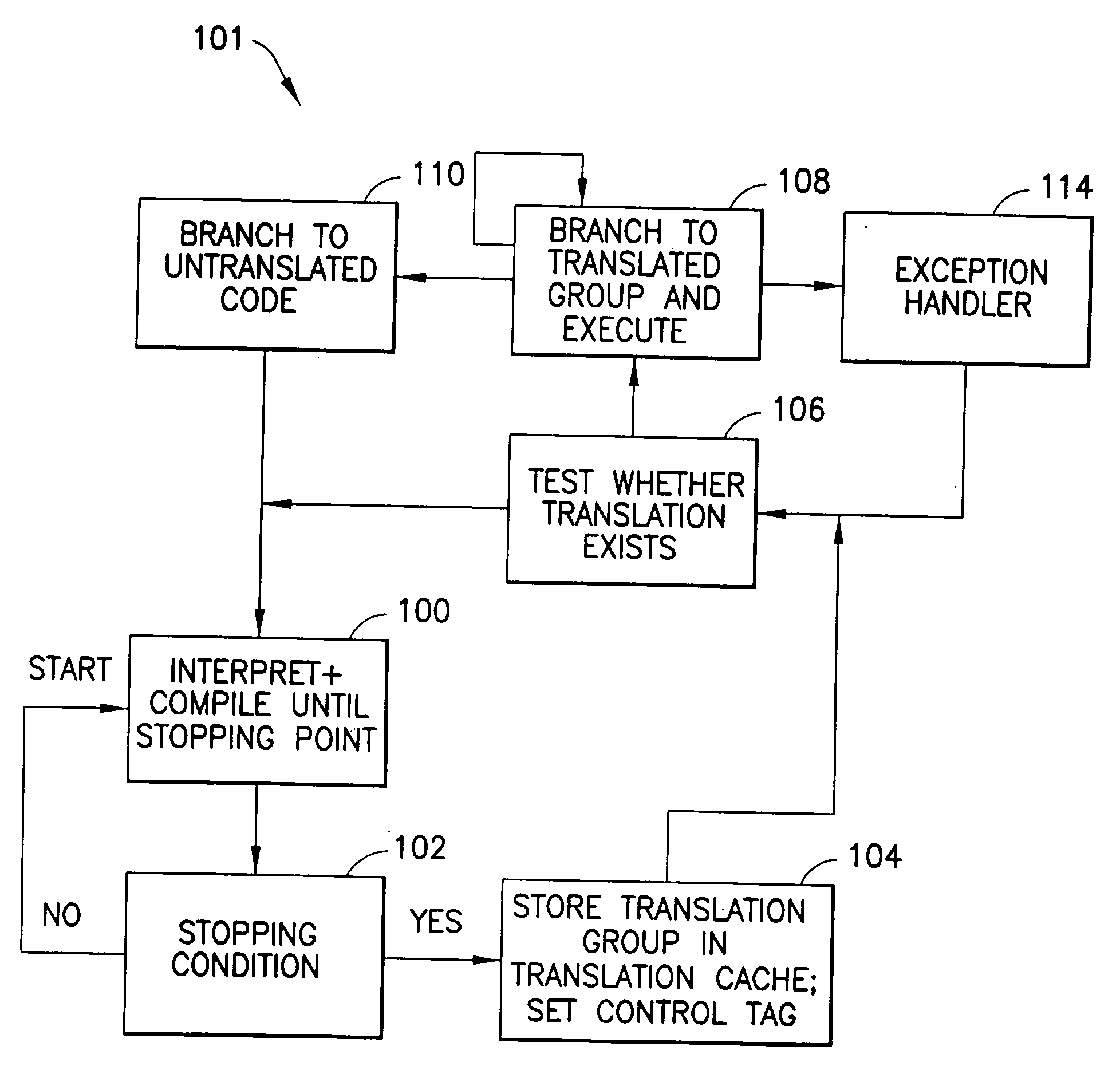
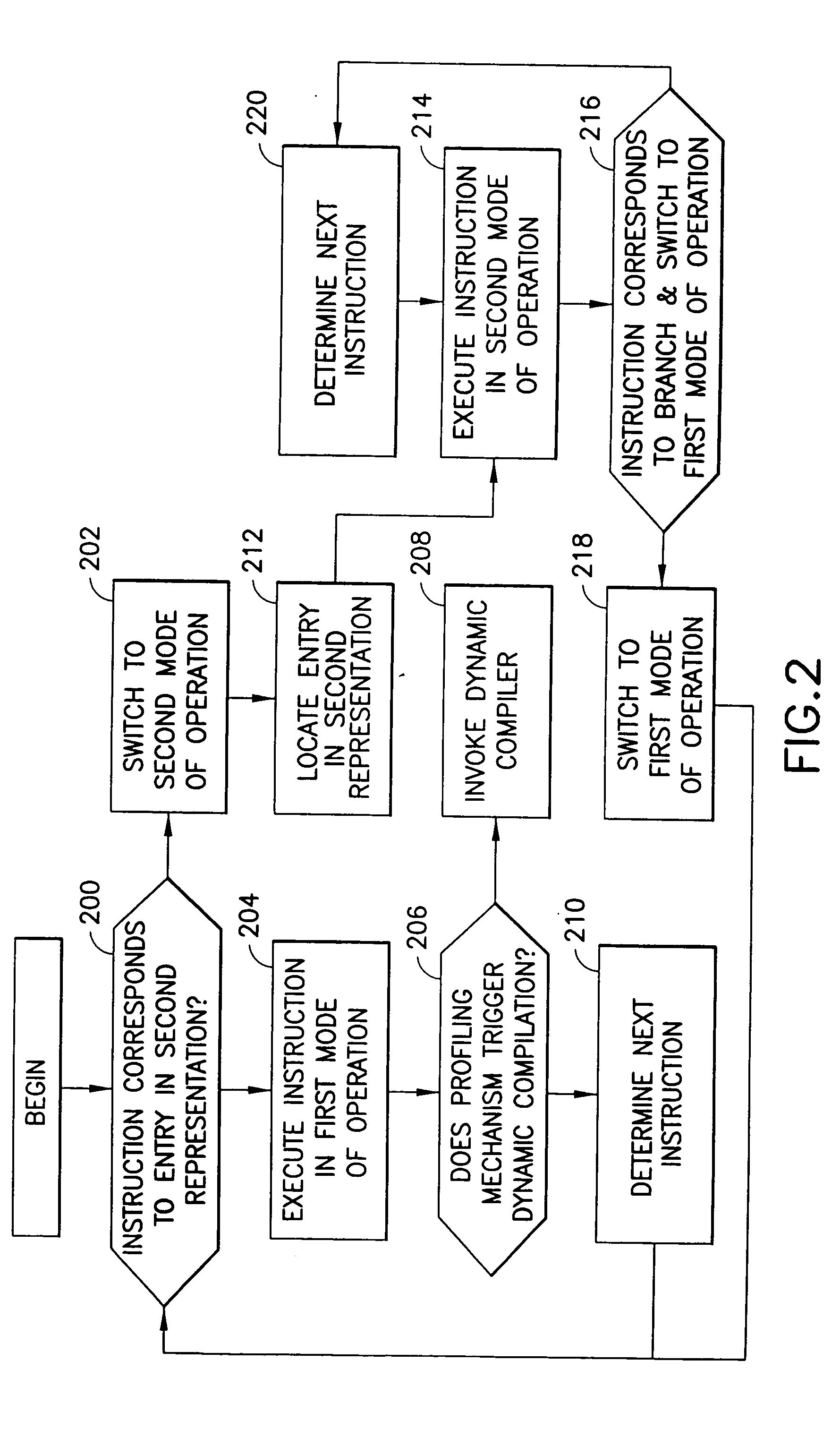
[0026] The present invention decouples the detection of code transfers (i.e., transfers from a first (migrant) representation to a second (native) representation) from the mapping of code addresses corresponding to the control transfer. By doing so, it is possible to exploit the different characteristics of the transfer decision and the actual transfer step. In particular, it is important that it be possible to determine quickly, for every instruction in the first representation, if a control transfer is possible to an entry point in a second representation of the instruction. This decision has to be performed without incurring any unnecessary overhead in the execution of code from the first program representation. Once a decision to transfer control is made, the address mapping between the current instruction in the first representation and an entry point in the second representation can be effected normally. It should be noted that although conceptually the lookup step is performe...


PUM


Abstract

In a dynamically compiling computer system, a system and method for efficiently transferring control from execution of an instruction in a first representation to a second representation of the instruction is disclosed. The system and method include the setting of a tag for entry points of each instruction in a first representation that has been translated to a second representation. The tag is stored in memory in association with each such instruction. When a given instruction in a first representation is to be executed, the tag is examined, and if it indicates that a translated version of the instruction has previously been generated, control is passed to execution of the instruction in the second representation. The second representation can be a different instruction set representation, or an optimized representation in the same instruction set as the original instruction.

Description

[0001] 1. Field of the Invention[0002] The present invention generally relates to computing systems employing dynamic compilation, such as dynamic optimization and binary translation techniques, and more particularly to a method and apparatus for transferring control from the execution of a portion of a first representation of a program to a portion of the program in a second representation of the program.[0003] 2. Description of the Related Art[0004] Dynamic optimization is the transformation of a program's description from a first representation in a particular instruction set--this usually being the original representation as generated by the programmer and his tools--into a second representation of the program in the same instruction set, the second representation being able to better exploit the characteristics of a given microprocessor implementing said instruction set given the characteristics of the particular instance of the program. Dynamic optimization employs a number of...

Claims


Application Information

Patent Timeline
IPC IPC(8): G06F9/318G06F9/45
CPCG06F9/30174G06F9/45516G06F9/3808
Inventor ALTMAN, ERIK R.EBCIOGLU, KEMALGSCHWIND, MICHAEL KARLLUICK, DAVID ARNOLD
Owner IBM CORP
Learn More