Optical branching device

a branching device and optical fiber technology, applied in the field of optical branching devices, can solve the problems of troublesome connection operation of optical fiber and input optical waveguide, inability to avoid leaky modes, and difficulty in preparing an optimum design in view of actual leaky modes

Inactive Publication Date: 2004-03-11
TDK CORPARATION
View PDF6 Cites 2 Cited by
  • Summary
  • Abstract
  • Description
  • Claims
  • Application Information

AI Technical Summary

Problems solved by technology

Accordingly, in the connection structure of the input optical waveguide and the optical fiber, it is impossible to avoid the occurrence of a leaky mode caused by mismatching of mode solution distributions of those.
Since the magnitude of the occurring leaky mode also includes a previously expected coupling loss and a coupling loss which can occur by fiber connection or the like, it is very difficult to prepare an optimum design in view of the actual leaky mode.
Thus, there arises a problem that the connection operation of the optical fiber and the input optical waveguide becomes troublesome and yield becomes low.
Although this mismatching loss can be easily decreased by optimizing the shape of the rectangular optical waveguide, since the optimized optical waveguide structure has a large minimum bend radius, there arises a problem that the scale of the device itself is increased.
Although the "leaky light" of the leaky mode is apt to attenuate as compared with the waveguide mode, in the case where the refractive index distribution is changed and the state of the propagation mode is changed in a region where it does not sufficiently attenuate, there is a case where part of the leaky light is recombined with the propagation mode, or interference occurs between the leaky mode and the propagation mode.
The meander of the light intensity along the optical waveguide direction is due to the interference between the leaky mode and the propagation mode, and this is the essential cause of deterioration of the branching characteristic in the optical branching device.
Since the magnitude of the leaky mode includes the previously expected coupling loss and the coupling loss which can occur in the optical fiber connection or the like, it is very difficult to prepare an optimum design in view of the actual leaky mode.
If the optimum design is not performed, the branching ratio of the optical branching device varies by a subtle difference of the optical fiber connection state, and the lowering of yield is caused, and further, the troublesome of light axis alignment is also caused.

Method used


Image

  • Optical branching device
  • Optical branching device
  • Optical branching device

Examples


Embodiment Construction

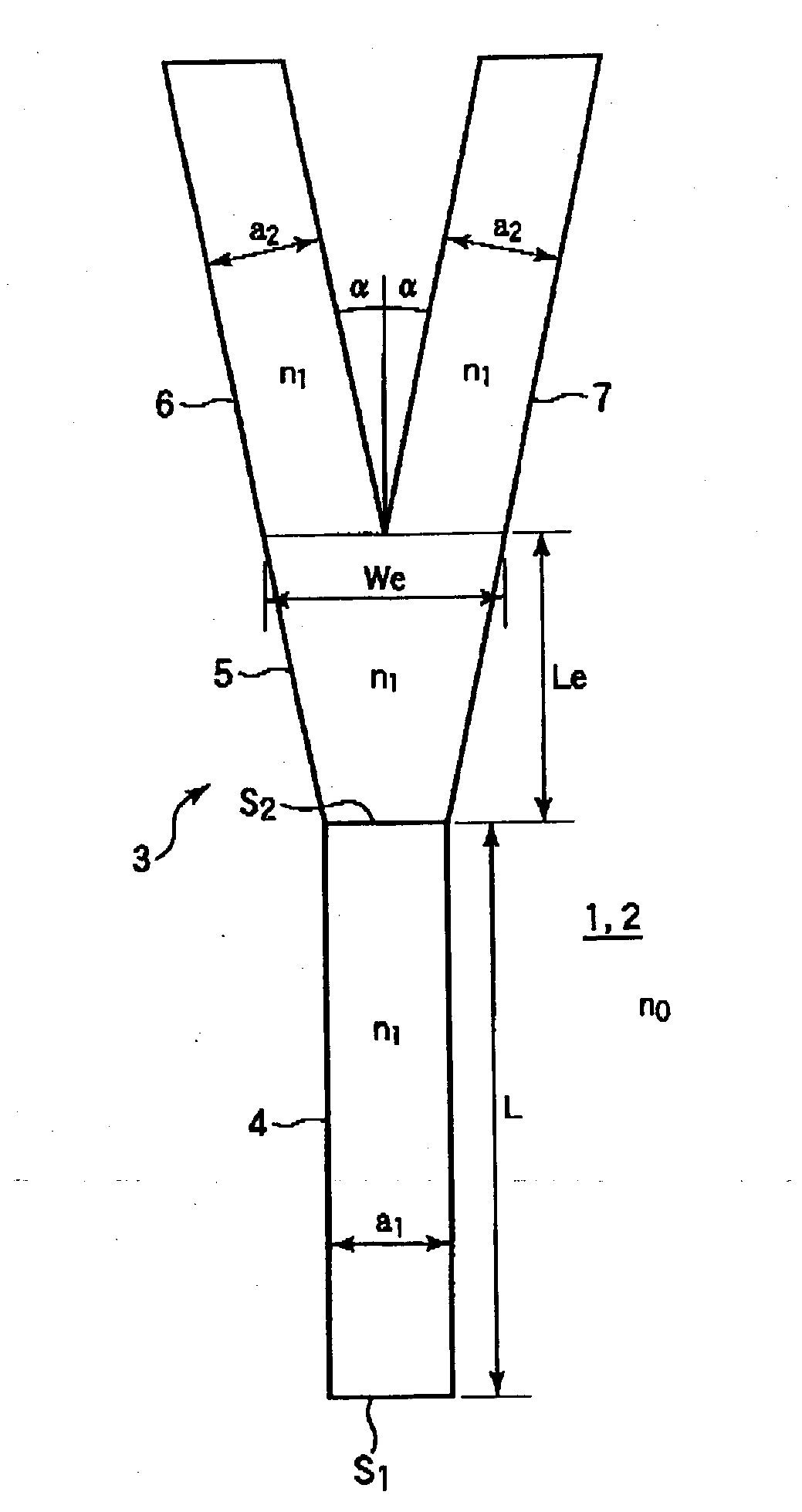
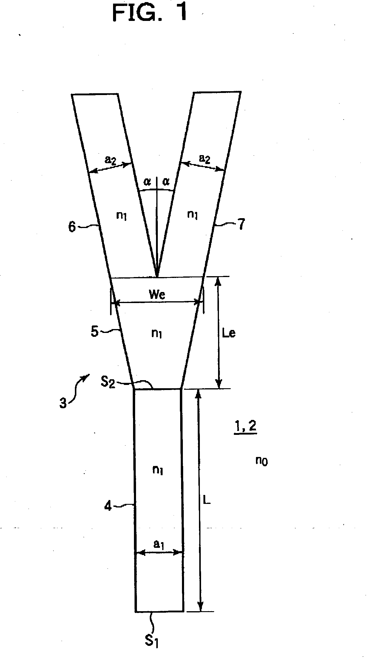
[0040] Next, a concrete example will be described. When a specific refractive index difference .DELTA.n is made .DELTA.n=0.4%, a core dimension in which a single mode occurs is 7.5 (.mu.m).times.7.5 (.mu.m). As the structure of the optical branching device, the width of the incident optical waveguide 4 is a.sub.1=7.5 .mu.m, the length of the tapered optical waveguide 5 is Le=180 .mu.m, and the width of the end face is We=15 .mu.m. The width of each of the branching optical waveguides 6 and 7 is a.sub.2=7.5 .mu.m, and the branching angle is .alpha.=0.4.degree..

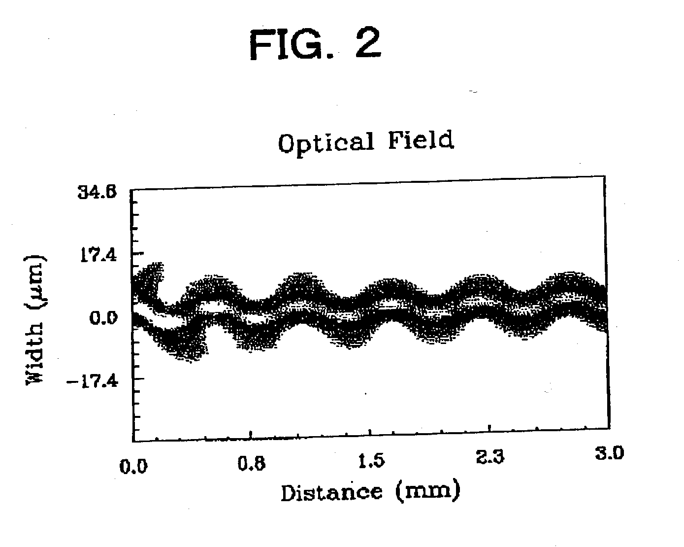
[0041] The calculation of a loss between the input and output ports (output light power / input light power) was made by the BPM (beam propagation method). In order to calculate the influence of leaky light, an initial excitation light distribution was made to have a Gaussian shape, and an offset (.diamond-solid. 0.2 .mu.m, .box-solid. 0.4 .mu.m) was given to the center axis of the optical waveguide to intentionally generate a mo...


PUM


Abstract

The invention relates to an optical branching device connected to a light output end face of an optical waveguide device or an optical branching device and for branching input light, and has an object to provide the optical branching device in which optical axis alignment is easy and the lowering of yield is suppressed. The optical branching device comprises an input optical waveguide for outputting light inputted from a light input end face S1 to a light output end face S2, a tapered optical waveguide having one end face connected to the light output end face S2 and a width expanding at a predetermined angle, and branching optical waveguides connected to the other end face of the tapered optical waveguide at a predetermined branching angle, in which when a propagation constant of a leaky mode is betaL, a propagation constant of a fundamental mode is betaO, a meander period is Lambda, and Lambda=2pi / (betaO-betaL), an optical waveguide length L from a position which becomes a cause of occurrence of the leaky mode to the light output end face S2 is substantially integer times as Lambda / 2.

Description

[0001] 1. Field of the Invention[0002] The present invention relates to an optical branching device connected to a light output end face of an optical waveguide device or another optical branching device for branching input light.[0003] 2. Description of the Related Art[0004] A general optical branching device is comprised of an input optical waveguide, a taper-shaped transition region for adiabatically changing a light distribution, and respective branching optical waveguides.[0005] Although the optical branching device is designed so that optical powers propagated to the respective branching optical waveguides have desired values, a measured value of a branching characteristic of a fabricated optical branching device often becomes a value different from a calculated value of the branching characteristic. In an actual optical branching device, a light output end face of an optical fiber is connected to a light input end face of an input optical waveguide, however, while a section o...

Claims


Application Information

Patent Timeline
Patent Type & Authority Applications(United States)
IPC IPC(8): G02B6/122G02B6/125
CPCG02B6/125
Inventor HANASHIMA, NAOKIKINERI, TOHRU
Owner TDK CORPARATION
Why Eureka
Try Eureka