
Method for judging effective cavity mode of resonant cavity enhanced photodetector without upper reflector

A technology of photodetectors and mirrors, which is applied in the measurement of scattering characteristics, circuits, electrical components, etc., can solve the problems of cavity mode half-height width, leaky mode, etc., and achieve the effect of high quantum efficiency

Inactive Publication Date: 2010-12-15
INST OF SEMICONDUCTORS - CHINESE ACAD OF SCI
View PDF0 Cites 4 Cited by
  • Summary
  • Abstract
  • Description
  • Claims
  • Application Information

AI Technical Summary

Problems solved by technology

[0014] However, the problem with this design is that due to the absence of the upper DBR limit, the reflection spectrum of the detector often cannot form a high-quality flat high anti-band, and there are many resonant cavity modes in the reflection spectrum, and the cavity mode The FWHM is also larger
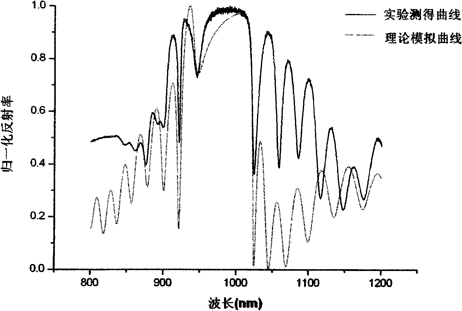
This in itself brings certain difficulties to us in selecting the cavity mode with the best resonance performance. The biggest problem is that, due to the limitation of the upper DBR, the strong absorption of the active absorption layer implanted in the cavity will also give the reflection of the detector Leaky modes similar to cavity modes

Method used


Image

  • Method for judging effective cavity mode of resonant cavity enhanced photodetector without upper reflector
  • Method for judging effective cavity mode of resonant cavity enhanced photodetector without upper reflector
  • Method for judging effective cavity mode of resonant cavity enhanced photodetector without upper reflector

Examples


Embodiment Construction

[0032] specific implementation plan

[0033] The present invention will be further described below in conjunction with example

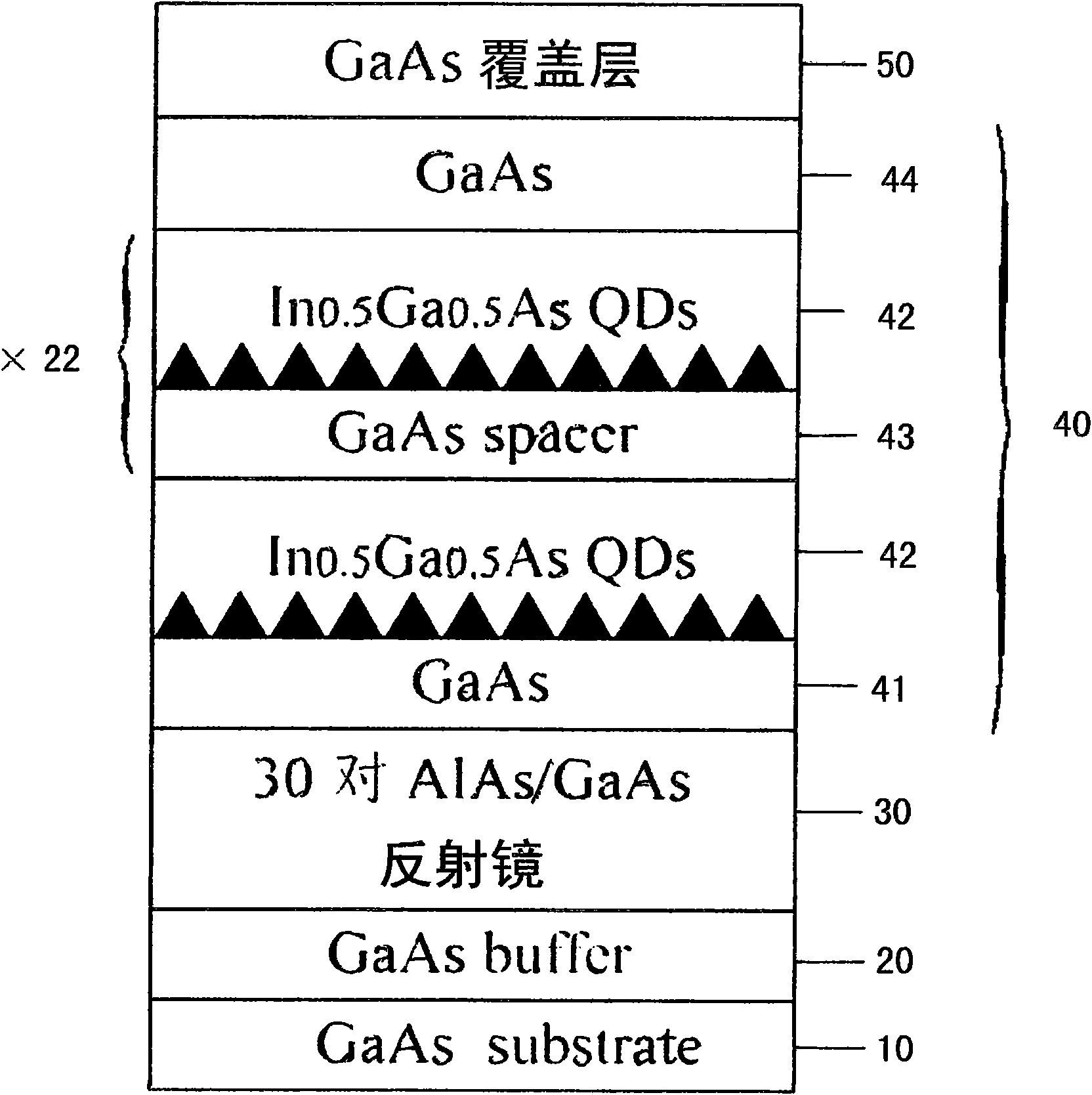
[0034] Step 1: The structure of our mirror-less resonator-enhanced photodetector is designed as figure 1 shown. The detector structure includes a substrate 10, a buffer layer 20, a lower reflector 30, a cavity 40, and a top cladding layer 50, wherein the lower reflector is composed of 30 pairs of AlAs / GaAs, and the active region in the cavity 40 is partially composed of 23 A group of InGaAs quantum dots 42 and a GaAs spacer layer 43 are formed, and the lower GaAs layer 41 and the upper GaAs layer 44 are GaAs bulk materials constituting the cavity. The central working wavelength of the detector is designed to be around 1 micron, and the designed detector structure is grown by MBE equipment.

[0035] Wherein the substrate 10 of the device structure, the buffer layer 20, the main body of the cavity 40 and the top cladding layer 50 are made of gallium...


PUM


Abstract

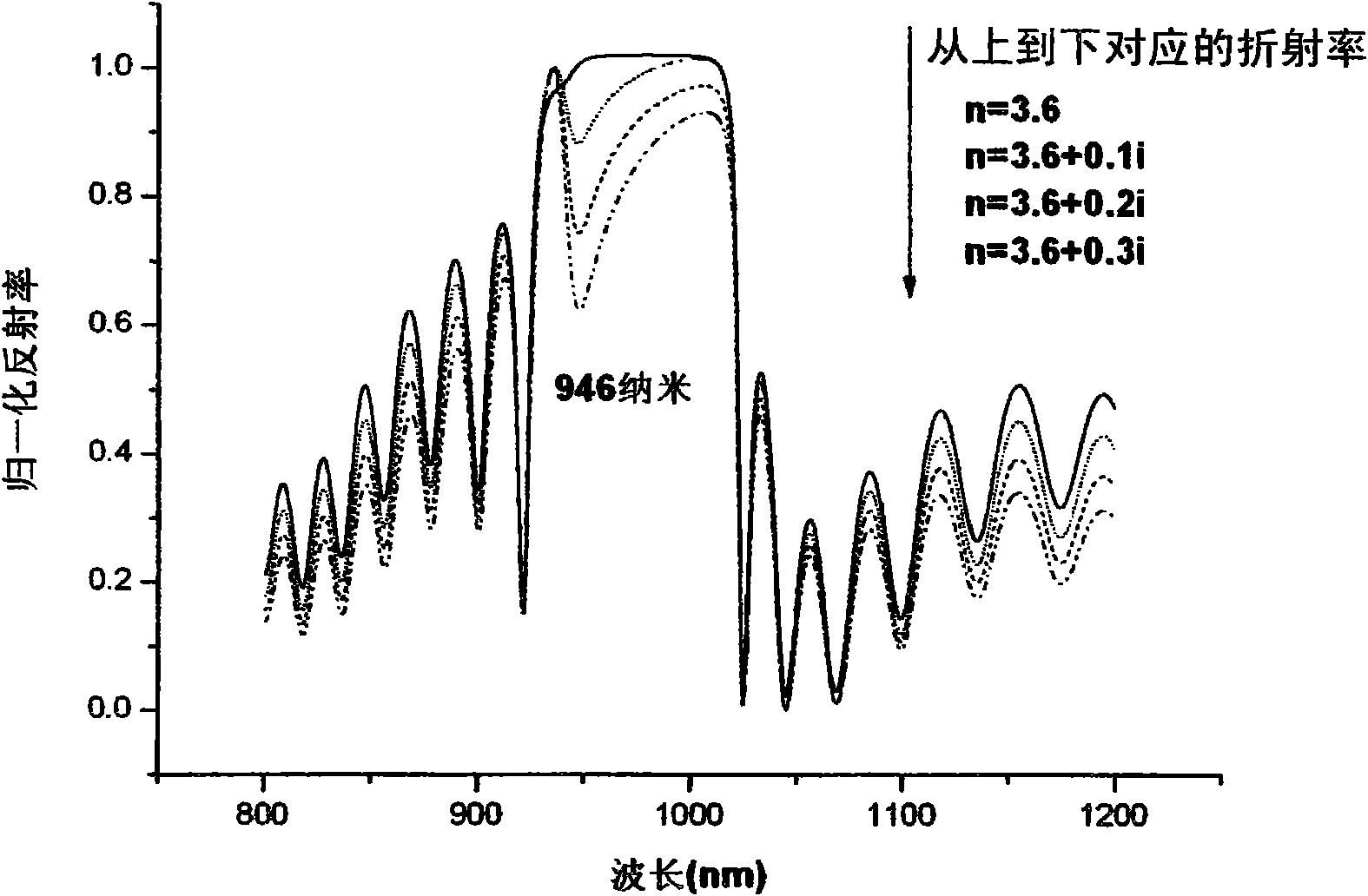
The invention discloses a method for judging an effective cavity mode of a resonant cavity enhanced photodetector without an upper reflector, which comprises the following steps: designing a structure of the resonant cavity enhanced photodetector without the upper reflector to form a detector sample; growing the designed detector sample, measuring the reflection spectrum of the sample by a spectrometer and marking the leaky modes of a high-reflectivity belt area in the reflection spectrum; editing a simulation program according to the principle of an optical transmission matrix and simulating to obtain a theoretically simulated reflection spectrum which is completely consistent with the designed resonant cavity enhanced photodetector without the upper reflector in terms of structure and layer thickness; adjusting the thickness of each layer of the reflector and the cavity in the simulation program so that the simulated reflection spectrum is always consistent with the reflection spectrum measured by test; then changing the absorption coefficient of an absorption layer in the simulation program and observing the change of each leaky mode in the simulated reflection spectrum, wherein the leaky mode deriving from the resonant cavity mode, namely the cavity mode, does not changes at the same time, so as to judge whether the leaky modes in the reflection spectrum of the resonant cavity enhanced photodetector without the upper reflector are from active area absorption or from the cavity mode.

Description

technical field [0001] The invention relates to the technical field of resonator-enhanced photodetectors, in particular to the technical field of resonator-enhanced photodetectors without top mirrors, and provides a method for determining the effective cavity mode of resonator-enhanced photodetectors without top mirrors. . The invention can be applied to the actual detection technology of the resonant cavity enhanced photodetector without the mirror. Background technique [0002] The 21st century is the century of high-tech information. The information age is characterized by a huge explosion of information, very fast information transmission, and very rapid information processing. The quantification mark is 3T: optical communication rate > 1Tbit / s; computer speed > 1Tbit / s s; CD storage density> 1Tbit / inch2. To realize 3T, it is necessary to rely on optoelectronic technology that will be further developed in this century from the last century. Photon is one of t...

Claims


Application Information

Patent Timeline
IPC IPC(8): G01M11/02G01N21/55H01L31/09
Inventor 孙晓明郑厚植章昊
Owner INST OF SEMICONDUCTORS - CHINESE ACAD OF SCI
Learn More