
System and Method for Diffractive Steering of Electromagnetic Radiation

Active Publication Date: 2019-03-28
CHARLES STARK DRAPER LABORATORY
View PDF0 Cites 5 Cited by
  • Summary
  • Abstract
  • Description
  • Claims
  • Application Information

AI Technical Summary

Benefits of technology

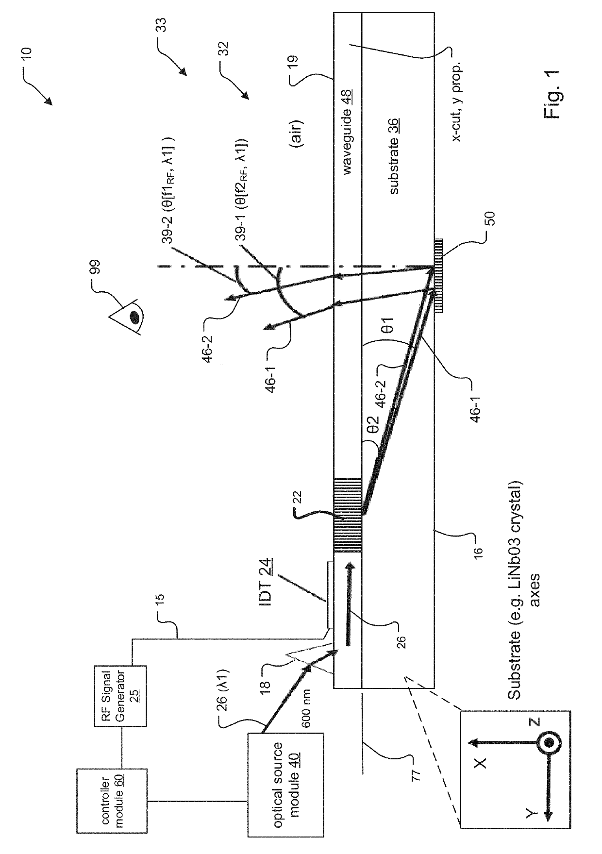
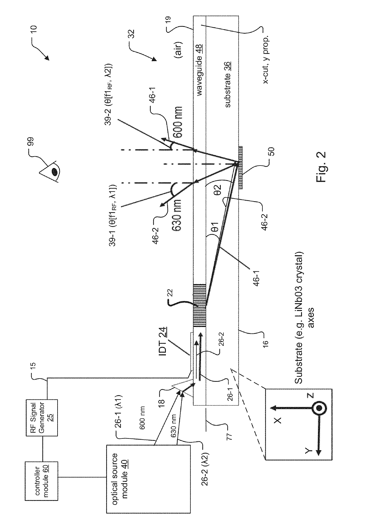
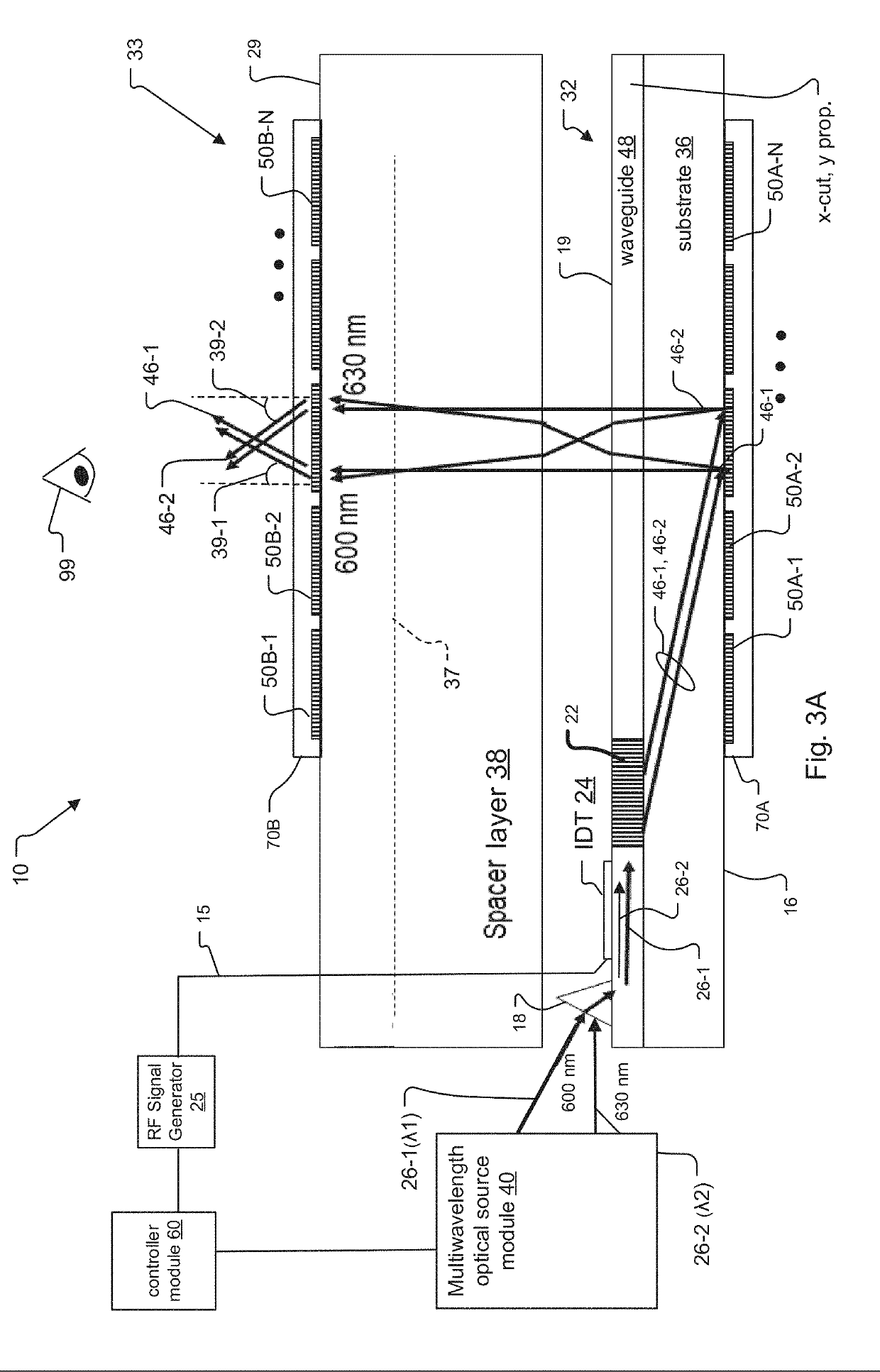
The present invention takes advantage of the way light is influenced by its wavelength in acousto-optic modulators like SAW modulators. This allows for better control over the light beams and a wider range of angles. The invention uses a combination of radio frequency and wavelength-based steering, as well as diffractive structures like gratings and lenses to improve the angular dynamic range. By doing this, the system can produce high-quality optical images with less distortion.

Problems solved by technology

Existing diffractive modulators, specifically those which steer or otherwise shape light, have long been known to suffer disadvantages including: narrow beam steering angle, discretized rather than continuous selection of steering angle(s), unintentional broadening of a single output “ray,” and excessive device volume.

Method used


Image

  • System and Method for Diffractive Steering of Electromagnetic Radiation
  • System and Method for Diffractive Steering of Electromagnetic Radiation
  • System and Method for Diffractive Steering of Electromagnetic Radiation

Examples


Embodiment Construction

[0030]The invention now will be described more fully hereinafter with reference to the accompanying drawings, in which illustrative embodiments of the invention are shown. This invention may, however, be embodied in many different forms and should not be construed as limited to the embodiments set forth herein; rather, these embodiments are provided so that this disclosure will be thorough and complete, and will fully convey the scope of the invention to those skilled in the art.

[0031]As used herein, the term “and / or” includes any and all combinations of one or more of the associated listed items. Further, the singular forms and the articles “a”, “an” and “the” are intended to include the plural forms as well, unless expressly stated otherwise. It will be further understood that the terms: includes, comprises, including and / or comprising, when used in this specification, specify the presence of stated features, integers, steps, operations, elements, and / or components, but do not pre...


PUM


Abstract

A light steeling system and method for diffractive steering of electromagnetic radiation such as visible light is disclosed. Embodiments of the light steering system include leaky-mode SAW modulators as light modulator devices. The SAW modulators preferably include reflective diffractive gratings. The gratings are mounted to / patterned upon an exit face that opposes an exit surface of the SAW modulator, in one example. Steering of light signals emitted from the SAW modulators in these systems can be accomplished by varying wavelength of light signals introduced to the SAW modulators, and / or by varying frequency of RF drive signals applied to the SAW modulators. In addition, light field generators that incorporate SAW modulators of the proposed light steering system within displays of the light field generators are also disclosed.

Description

RELATED APPLICATIONS[0001]This application claims the benefit under 35 USC 119(e) of U.S. Provisional Application No. 62 / 564,548, filed on Sep. 28, 2017, which is incorporated herein by reference in its entirety.BACKGROUND OF THE INVENTION[0002]Acousto-optic modulators (AOMs) are a type of diffractive modulator that use diffraction to direct light. They show promise as components of light display systems for generating light fields as are required for holographic displays and other applications. One class of AOMs are termed surface acoustic wave (SAW) optical modulators. These modulators can provide controllable sub-holograms from which a light field can be constructed.[0003]One type of SAW modulator is the guided-to-leaky-mode device fabricated using lithium niobate as described, for example, in Hinkov et al., Collinear Acoustooptical TM-TE Mode Conversion in Proton Exchanged Ti:LiNbO3 Waveguide Structures, J. Lightwave Tech., vol. 6(6), pp. 900-08 (1988), Smalley et al., Anisotrop...

Claims


Application Information

Patent Timeline
IPC IPC(8): G02F1/335G02B6/293G03H1/22H04L27/20G02B6/35H04B10/50G02B27/22
CPCG02F1/335G02B6/29311G03H1/2294H04L27/2003G02B6/356H04B10/506G02B27/225G02F2203/24G02F2203/22
Inventor BYRNES, STEVEN J.FAVALORA, GREGG E.FRANK, IAN WARDKOPA, ANTHONYKORN, JEFFREY A.MOEBIUS, MICHAEL G.
Owner CHARLES STARK DRAPER LABORATORY
Learn More