Switchable damping mechanism for use in a stage apparatus

Inactive Publication Date: 2004-03-25
NIKON CORP
View PDF1 Cites 22 Cited by
  • Summary
  • Abstract
  • Description
  • Claims
  • Application Information

AI Technical Summary

Problems solved by technology

When the performance of a precision instrument is adversely affected, as for example by vibrations, products formed using the precision instrument may be improperly formed and, hence, function improperly.
For instance, a photolithography machine which is subjected to vibrations may cause an image projected by the photolithography machine to move, and, as a result, be aligned incorrectly on a projection surface such as a semiconductor wafer surface.
Further, vibrations may cause control problems during an acceleration portion of a scanning process or a scan.
Within a photolithography apparatus, vibrations may be particularly problematic, especially when the vibrations are excited to uncontrollable levels during the acceleration and the deceleration of components of the apparatus, such as a wafer table.
While such vibrations often cause accuracy issues during an acceleration or deceleration portion of an overall wafer scanning process, the same vibrations often do not significantly affect the accuracy of a constant velocity, or exposure portion, of a scan.
In other words, although vibrations may cause significant stage control problems during an acceleration or deceleration portion of an overall scanning process, vibrations generally do not significantly affect the ability to control the stage during an exposure portion of the scanning process.
However, the transient acceleration or deceleration effects which may remain from the acceleration portion of a scanning process may cause accuracy issues to arise during the exposure portion of the scanning process.
Transient effects which result from acceleration or deceleration of a wafer table may result in measurement

Method used


Image

  • Switchable damping mechanism for use in a stage apparatus
  • Switchable damping mechanism for use in a stage apparatus
  • Switchable damping mechanism for use in a stage apparatus

Examples


Embodiment Construction

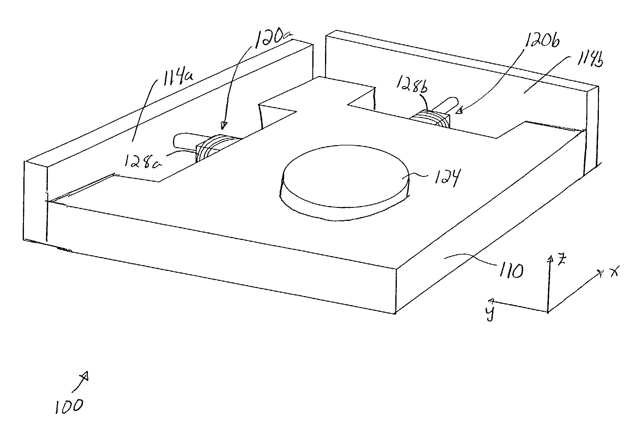
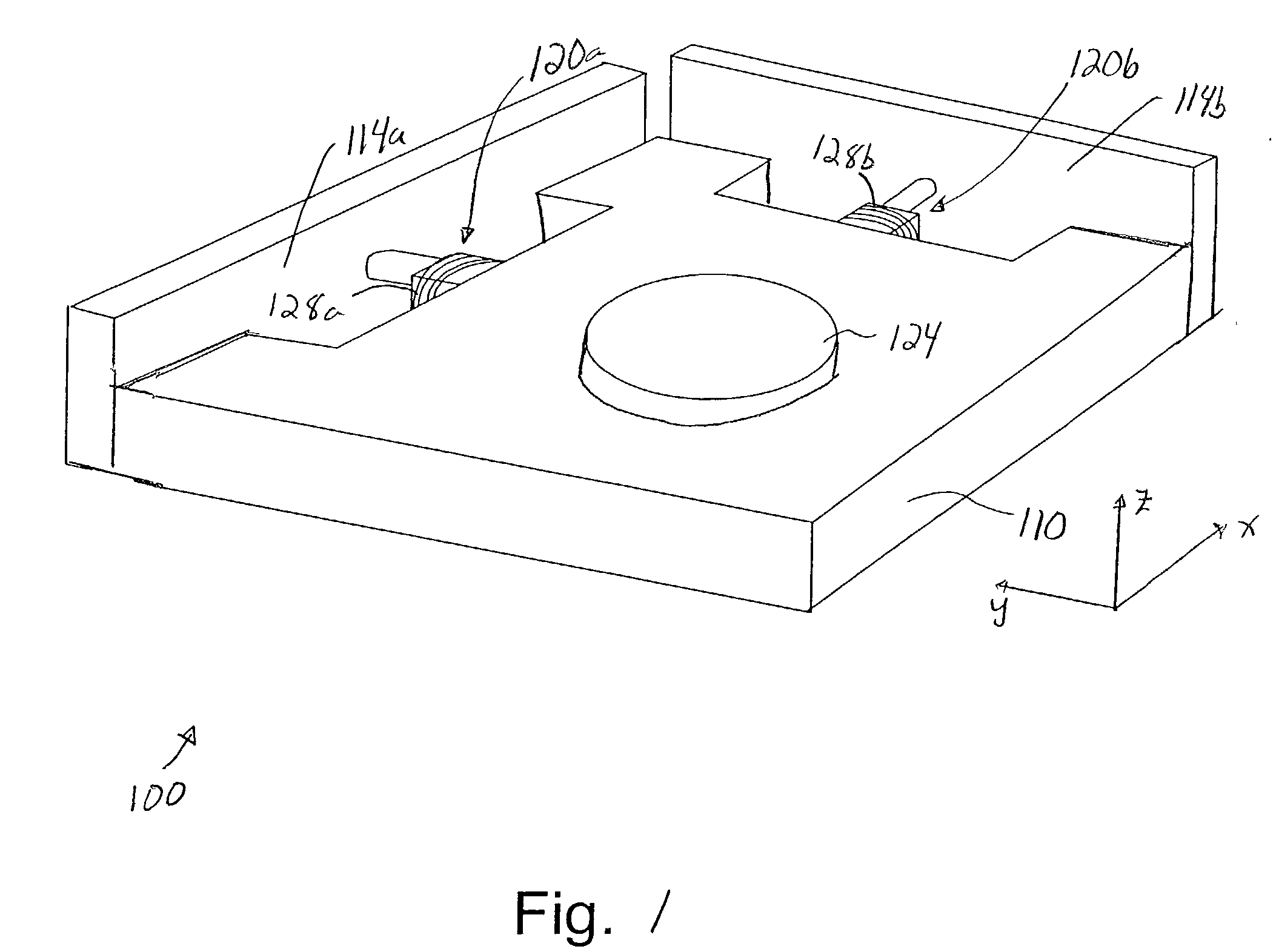
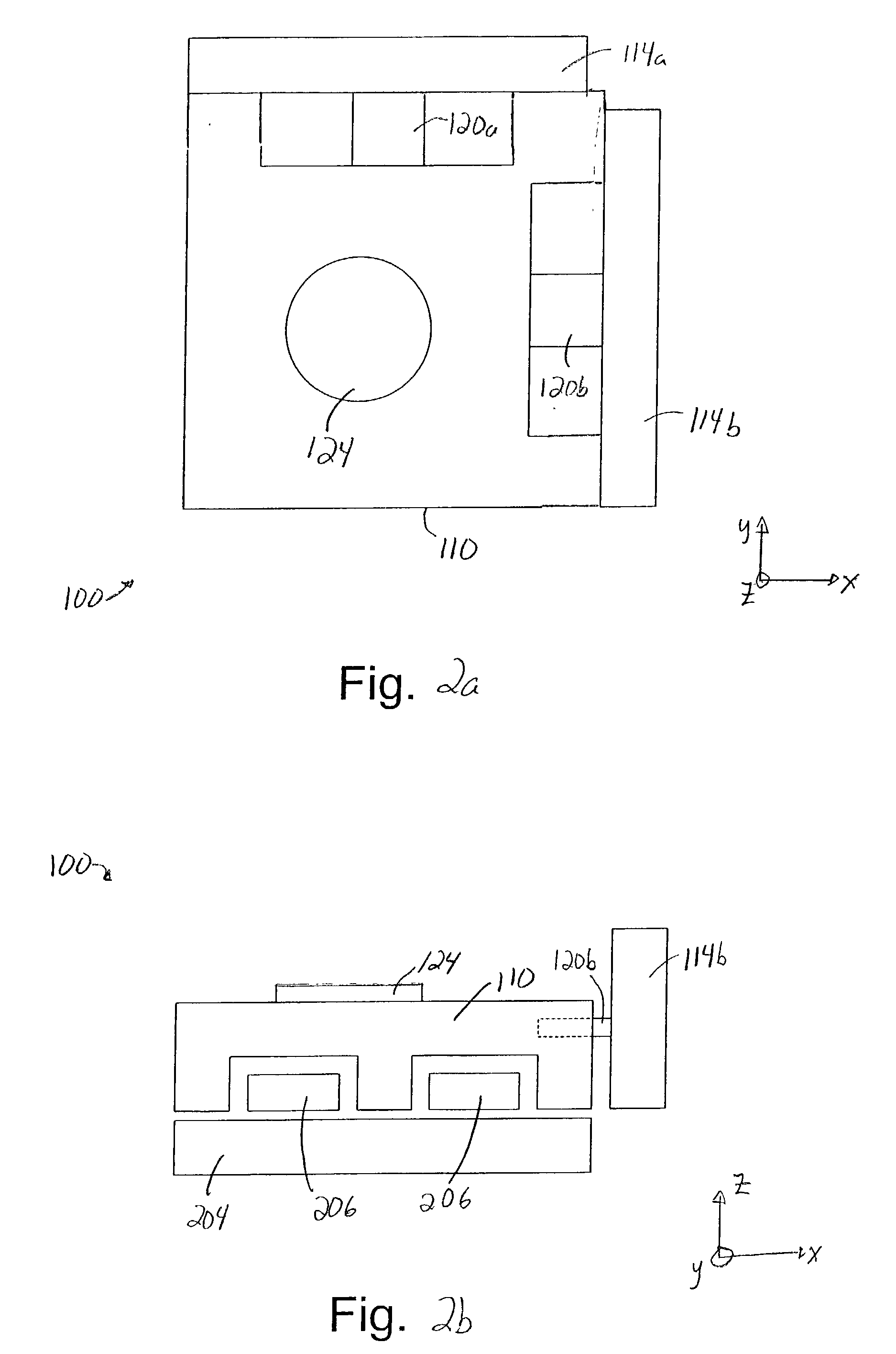
[0032] Reducing the effect of vibrations on a precision instrument during an acceleration or deceleration portion of a wafer scan process is generally necessary in order to enable a wafer table of the precision instrument to be accurately scanned. While passive damping solutions are effective in dissipating vibrational energy, passive damping solutions may cause the wafer table to distort during an exposure portion of the scan.

[0033] In order to enable vibrations to be damped during an acceleration or deceleration portion of a wafer scan substantially without causing significant distortion or deceleration, dampers which may be controlled or adjusted in real-time may be implemented within a precision instrument. Such dampers, e.g., magneto-rheological dampers, may be activated during acceleration or deceleration in order to damp vibrations such as mirror vibrations, and deactivated during exposure to substantially prevent a wafer table from experiencing significant distortion. In oth...


PUM


Abstract

Methods and apparatus for damping vibrations within a stage device using controllable dampers are disclosed. According to one aspect of the present invention, a method for adjusting an amount of resistance associated with a stage device which has a table, a first surface, and a coupler positioned substantially between the table and the first surface includes accelerating the table and applying a resistance between the table and the first surface when the table is accelerating. Applying the resistance includes providing a first adjustment to the coupler. The method also includes substantially removing the resistance from between the table and the first surface when the table is not accelerating, wherein the resistance is substantially removed by providing a second adjustment to the coupler. In one embodiment, the stage device further includes a first damper that is arranged to substantially damp an elastic body vibration of the wafer table.

Description

[0001] 1. Field of Invention[0002] The present invention relates generally to semiconductor processing equipment. More particularly, the present invention relates to a damping mechanism that reduces vibrations associated with a wafer table when the wafer table is accelerating, but does not adversely affect the wafer table during a wafer exposure process.[0003] 2. Description of the Related Art[0004] For precision instruments such as photolithography machines which are used in semiconductor processing, factors which affect the performance, e.g., accuracy, of the precision instrument generally must be dealt with and, insofar as possible, eliminated. When the performance of a precision instrument is adversely affected, as for example by vibrations, products formed using the precision instrument may be improperly formed and, hence, function improperly. For instance, a photolithography machine which is subjected to vibrations may cause an image projected by the photolithography machine t...

Claims


Application Information

Patent Timeline
IPC IPC(8): G03F7/20
CPCG03F7/70716G03F7/70758G03F7/70725
Inventor HAZELTON, ANDREW J.
Owner NIKON CORP
Why Eureka
Try Eureka