Position-control stage with onboard linear motor

a technology of linear motor and position control stage, which is applied in the direction of propulsion system, winding, manufacturing tools, etc., can solve the problems of difficult use, difficult arrangement, and prior driver units not ready for position control stages

Inactive Publication Date: 2004-04-01
NIPPON THOMPSON
View PDF7 Cites 26 Cited by
  • Summary
  • Abstract
  • Description
  • Claims
  • Application Information

AI Technical Summary

Problems solved by technology

Nevertheless, the driver unit constructed as stated earlier, because there is no center of turning inside the driver unit, is tough in arrangement and difficult to use.
Moreover, the prior driver unit is not ready for position-control stages because the field magnets should be arranged with large radius of curvatures.
Thus, the prior construction is hardly suited to every desired radius of curvature.
Like the prior circular linear motor recited previously, the prior motor for swinging motion constructed as stated earlier is also hardly suited to every desired radius of curvature, because both the field magnets and the armature windings must be made into the same sector of any desired curvature.
However, this sort of linear motor would become bulky in dimension.
Nevertheless, the table system with angular position control constructed as stated earlier, because of having no onboard linear motor, could not be made less in height by any means.
Thus, problems are parts or components are complicated in construction and position control lacks for precision.
Thus, it remains a major challenge to provide a slider unit advancing in conduction system for armature windings, selection of material for field magnet and fixture construction of sensor cords to make the slider unit less in weight, compact and simple in construction, far more precise in position control of the table relatively to the bed, large in angle allowed for angular movement in circular direction upon position control, reduced in height as low as possible, and inexpensive in production cost.

Method used


Image

  • Position-control stage with onboard linear motor
  • Position-control stage with onboard linear motor
  • Position-control stage with onboard linear motor

Examples


first embodiment

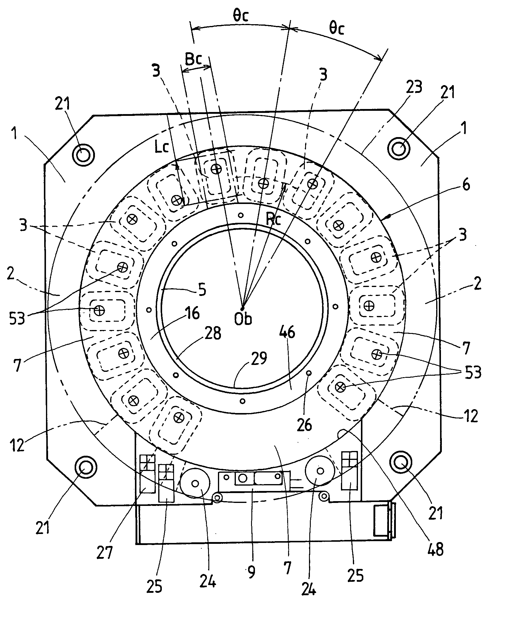
[0045] The armature winding 3 has a core made of, for example resin molding around which the winding turns are laid. The armature winding 3 may be constructed, for example using the armature winding as recited in Japanese Patent Laid-Open No. 2001-352744, which was filed for a senior invention of the same applicant as in the present application. Each armature winding 3 lies radially on a disc surface along a preselected curvature in juxtaposition with one another in circumferential direction. The total number of the armature windings 3 is multipliers of 3. They are held on the coil support 7 to complete the winding assembly 6. With the first embodiment discussed now, there are arranged fifteen armature windings 3 on the bed 1.

[0046] Each armature winding 3 lying radially on a disc surface along a preselected curvature in circular direction, as shown in FIG. 4, is made in a rectangular configuration when seen in plan view, longer sides of which constitute two coil sides effective to ...

second embodiment

[0062] the position-control stage, as seen from FIGS. 6 and 7, has a pair of specific linear motors 50 of minimum unit to increase the torque to drive the turntable 2 relatively to the bed 1. The minimum unit of the linear motor 50 is comprised of three armature windings 3 and five field magnets 4. The three armature windings 3 are fastened to the coil support 7 of sector, for example a quadrant in FIG. 6, with some threaded bolts screwed into holes, refer to FIG. 10, which are used to fasten together the armature windings 3 to complete the winding assembly 37. The field magnets 4 consisting of five poles are each held to the turntable 2 to complete a field magnet assembly 52 through a magnet support 40 of sectorial configuration, for example a quarter of a circle as in FIG. 7, which is attached underneath of the turntable 2. It will be thus understood that a pair of field magnet supports 40 secured underneath the turntable 2 to lay the five poles of field magnet thereon lies in opp...


PUM


Abstract

A position-control stage is disclosed which makes it possible to extend largely an angular movement in circular direction for position control, rendering the stage itself compact in construction, allowing to work with high precision in clean environment and further produce the stage with inexpensive cost. The position-control stage has an onboard linear motor composed of armature windings of primary side and field magnets of secondary side. The armature windings are each made in a hollow rectangle where winding turns are wound in the form of flat loop, and are circularly arranged on a disc surface of the bed along a preselected curvature in such a way lying in radial juxtaposition in circumferential direction. The field magnets are made in a flat shape and arranged underneath the turntable in such a pattern lying radially on a disc surface of the preselected curvature in opposition to the armature windings, with their unlike poles alternating in polarity along a circular direction.

Description

[0001] 1. Field of the Invention[0002] The present invention relates to a position-control stage with onboard linear motor, which has been extensively used in machinery including semiconductor and liquid display manufacturing equipment, measuring instruments, assembling machines, tool machines, industrial robots, conveyors and, more particularly, to a position-control stage in which an armature coil is installed in, for example, a stationary bed while a field magnet lies on a turntable.[0003] 2. Description of the Prior Art[0004] In recent years, current multi-axis stages and moving mechanisms such as X-Y plotters employed in the diverse technical fields using machinery as stated earlier have required more and more a slider unit, which is made compact or slim in construction and light in weight, and moreover able to operate with high propulsion, high speed and high response to provide high speed travel and precise position control for works, tools, articles and instruments. Linear m...

Claims


Application Information

Patent Timeline
Patent Type & Authority Applications(United States)
IPC IPC(8): B23Q5/28H01L21/68H02K3/47H02K29/10H02K41/03
CPCH02K3/47H02K2201/15H02K41/03H02K29/10
Inventor TSUBOI, TAKAAKIIDA, EIJIKANAZAWA, YOSHIHIKO
Owner NIPPON THOMPSON
Why Eureka
Try Eureka