
Linear motor apparatus

a technology of linear motors and motor components, applied in the direction of dynamo-electric converter control, program control, instruments, etc., can solve the problems of absolute sensor malfunction according to the situation, and achieve the effect of reliable initialization of the position information of the moving par

Inactive Publication Date: 2004-04-01
CANON KK
View PDF3 Cites 8 Cited by
  • Summary
  • Abstract
  • Description
  • Claims
  • Application Information

AI Technical Summary

Benefits of technology

0010] However, in the case of measurement of a moving part which moves in a long stroke by an absolute sensor, as the absolute sensor is particularly influenced with disturbance from an external environment in comparison with an interferometer or a linear encoder, the a...

Problems solved by technology

However, in the case of measurement of a moving part which moves in a long stroke by an absolute sensor, as the absolute sensor is particularly influenced with disturbance from an external environment in comparison with an interferometer or a linear encoder, the absolute sensor may malfunction according to circumstances.

Method used


Image

  • Linear motor apparatus
  • Linear motor apparatus
  • Linear motor apparatus

Examples


Embodiment Construction

[0020] Preferred embodiments of the present invention will now be described in detail in accordance with the accompanying drawings.

[0021]

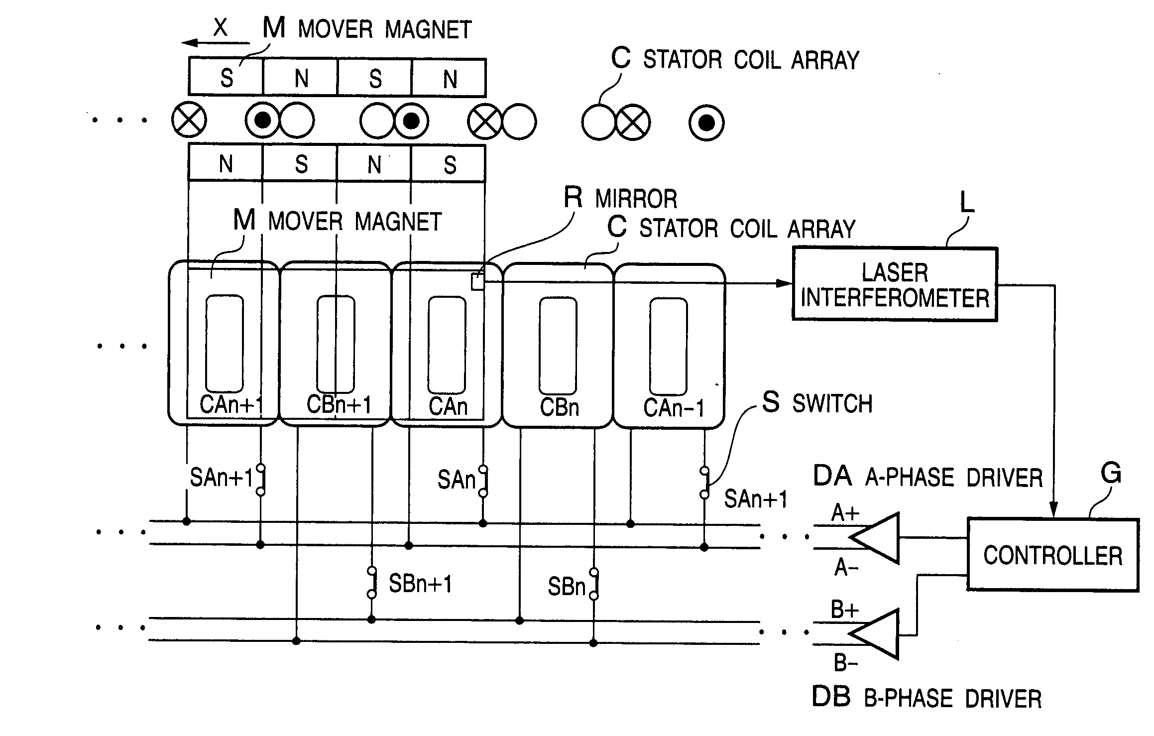
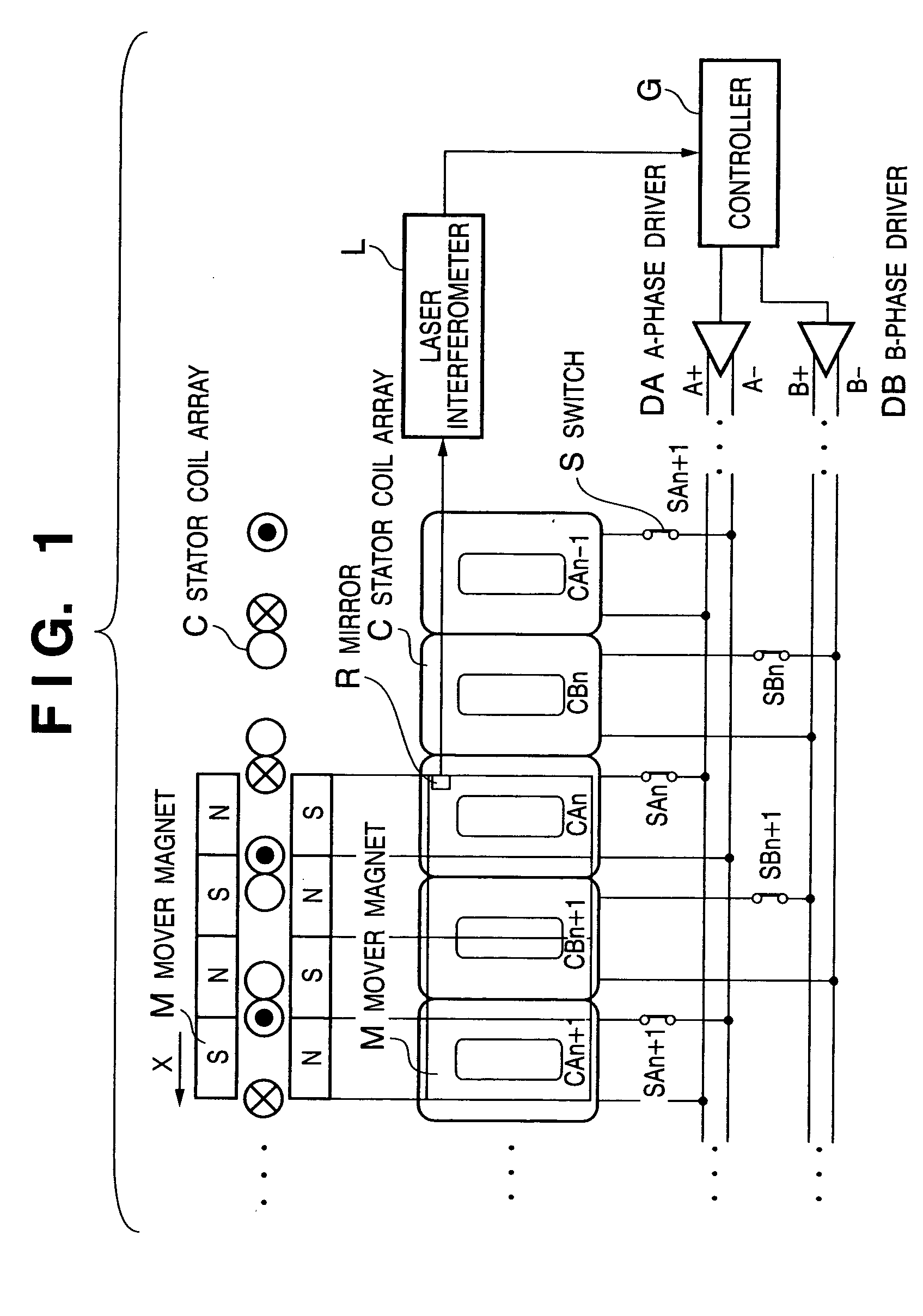
[0022] FIG. 1 shows the construction of a linear motor driving circuit according to a first embodiment of the present invention. In FIG. 1, alphabet M denotes a mover magnet; CAn-1, CAn and CAn+1, an A-phase coil array; CBn and CBn+1, a B-phase coil array; and SAn-1, SAn, SAn+1, SBn and SBn+1, switches to the respective A-phase and B-phase coils.

[0023] Further, alphabet L denotes an incremental laser interferometer; R, a reflecting mirror; DA, an A-phase driver; DB, a B-phase driver; and G, a controller. The interval between the respective same-phase coils is 1.5 times (integer+0.5) of the period of the magnetic field of the mover magnet M. Further, as disclosed in JPA Hei 11-341853, the respective coils are connected to the switches SA and SB such that the polarity is inverted by same-phase coil and at least one of the same-phase coils can be sel...


PUM


Abstract

A linear motor apparatus which drives a mover of a linear motor in a stable manner, by using only information on change of relative position, without using an absolute value sensor. The apparatus has a coil array of plural phases of coils and a magnet relatively movable to the coil array, plural drivers, at least one of which being provided for each phase, to feed a current to all the same phase coils of the coil array, a sensor for measuring a change of relative position of the magnet moved by the current to the coil array, and a controller to determine the polarity of the current applied to the same phase coils based on the change of the relative position measured by the sensor, and apply a drive current to drive the magnet in a desired direction to the same phase coils.

Description

FIELD OF THE INVENTION[0001] The present invention relates to a linear motor apparatus, and more particularly, to a linear motor apparatus utilized in an exposure apparatus.BACKGROUND OF THE INVENTION[0002] In a moving magnet type exciting linear motor, a mover is a magnet and a driving electric wire is provided on the stator side. In this arrangement, as the wire under no stress is not broken and heat generation is made on the stator side, cooling can be easily made by coolant or the like. Accordingly, this linear motor is used in various fields including a semiconductor fabrication apparatus requiring high reliability and accuracy.[0003] In a semiconductor exposure apparatus, for the sake of improvement in throughput, it is necessary to increase the size of a substrate (wafer) on which the pattern of a reticle is transferred, and to improve an acceleration and maximum speed of the linear motor. From this background, as a longer stroke in comparison with the size of the mover is re...

Claims


Application Information

Patent Timeline
IPC IPC(8): H01L21/027G03F7/20H02K29/06H02K41/02H02K41/03
CPCG03F7/70758G05B2219/41337H02P25/06H02K41/03H02K29/06H02P25/062
Inventor SATO, MIKIO
Owner CANON KK
Learn More