Method and apparatus for power level control of a display device

a display device and power level control technology, applied in the field of methods and apparatus for power level control of display devices, can solve problems such as accepting low-quality gray scale portrayals, and achieve the effects of reducing overall power consumption, less energy, and low luminan

Inactive Publication Date: 2004-04-01
INTERDIGITAL MADISON PATENT HLDG
View PDF0 Cites 14 Cited by
  • Summary
  • Abstract
  • Description
  • Claims
  • Application Information

AI Technical Summary

Benefits of technology

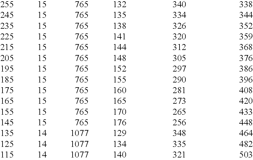
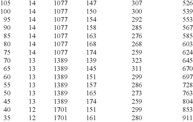
0028] Picture having a lot of energy (e.g. full-white page) will be displayed with a lower luminance to reduce the overall power consumption. This luminance will specify the maximal power consumption of the panel. Obviously, when the picture disposes of less energy, more luminance can be produced without overstressing the power supply (same maximal power consumption).

Problems solved by technology

This had the additional disadvantage, of allowing only a reduced number of discrete power levels (about 20), and of accepting a low-quality gray scale portrayal.
This was due to the fact that it was difficult, for most of the power levels, to distribute, the available discrete number of sustains, among the available number of sub-fields, keeping the relative sub-field weighting correct.

Method used


Image

  • Method and apparatus for power level control of a display device
  • Method and apparatus for power level control of a display device
  • Method and apparatus for power level control of a display device

Examples


Embodiment Construction

[0047] The principle structure of a plasma cell in the so-called matrix plasma display technology is shown in FIG. 1.

[0048] Reference number 10 denotes a face plate made of glass. With reference number 11 a transparent line electrode is denoted. The back plate of the panel is referenced with reference number 12. There are two dielectric layers 13 for isolating face and back plate against each other. In the back plate are integrated colour electrodes 14 being perpendicular to the line electrodes 11. The inner part of the cells consists of a luminous substance 15 (phosphorous) and separators 16 for separating the different coloured luminescent materials (green 15A) (blue 15B) (red 15C). The UV radiation caused by the discharge is denoted with reference number 17. The light emitted from the green phosphorous 15A is indicated with an arrow having the reference number 18. From this structure of a PDP cell it is clear, that there are three plasma cells necessary, corresponding to the thre...


PUM


Abstract

Plasma Display Panels (PDP) are becoming more and more interesting for TV technology. One important criterion for picture quality is the Peak White Enhancement Factor (PWEF). From a previous patent application of the applicant it is known to have a table of power level modes in a control unit for the display device. The average picture power value is measured and a corresponding power level mode will be selected from the table for sub-field coding. The power level modes have been made variable in respect to a number of parameters, namely: the number of sub-fields the sub-field type the sub-field positioning the sub-field weight the sub-field pre-scaling a factor for the sub-field weights which is used to vary the amount of small pulses generated during each sub-field. According to the invention it is now proposed to use one or both of the following parameters in addition for varying the power level modes: the sustain frequency the sustain pulse slope.

Description

[0001] The invention relates to a method and apparatus for power level control of a display device.[0002] More specifically the invention is closely related to a kind of video processing for improving the picture quality of pictures which are displayed on displays like plasma display panels (PDP), and all kind of displays based on the principle of duty cycle modulation (pulse width modulation) of light emission.[0003] The plasma display technology now makes it possible to achieve flat colour panels of large size and with limited depth without any viewing angle constraints. The size of the displays may be much larger than the classical CRT picture tubes would have ever been allowed.[0004] Referring to the latest generation of European TV sets, a lot of work has been made to improve its picture. quality. Consequently, there is a strong demand, that a TV set built in a new technology like the plasma display technology has to provide a picture so good or better than the old standard TV ...

Claims


Application Information

Patent Timeline
Patent Type & Authority Applications(United States)
IPC IPC(8): G09G3/288G09G3/28G09G3/296G09G1/00G09G3/294H04N5/66G09G3/20
CPCG09G2320/0626G09G2360/16G09G3/2944G09G3/296
Inventor CORREA, CARLOSWEITBRUCH, S?EACUTE, BASTIENROTH, HARALD
Owner INTERDIGITAL MADISON PATENT HLDG
Why Eureka
Try Eureka