Deskew circuit and disk array control device using the deskew circuit, and deskew method

a control device and circuit technology, applied in the direction of generating/distributing signals, instruments, recording signal processing, etc., can solve the problems of difficult to correct the clock to a position that allows all data to be read correctly, and the technology is not a method of transferring clock and data in parallel

Inactive Publication Date: 2004-04-08
HITACHI LTD
View PDF8 Cites 66 Cited by
  • Summary
  • Abstract
  • Description
  • Claims
  • Application Information

AI Technical Summary

Problems solved by technology

However, phases are matched to an external clock supplied to both the transmitting and receiving sides, and the technology therefore is not a method to transfer clock and data in parallel.
Although this method is effective when the transfer speed is slow and data pulse width is wide, it is difficult to correct the clock to a position that allows all data to be read correctly when the transfer speed is fast and the data pulse width is narrow.
This becomes even more difficult when taking into consideration the junction temperature fluctuations of an LSI that has a built in circuit that makes such an adjustment, power source voltage fluctuations, flip-flop set-up time and hold time.
However, the skew is larger and correcting the clock becomes very difficult when the transmission distance is long (e.g., approximately dozens to 100 cm), such as in a backplane.
Skew adjustment becomes difficult when the transmission distance is long as in a backplane, and this also sets a limit to the transfer speed and makes high-speed transfer impossible.

Method used


Image

  • Deskew circuit and disk array control device using the deskew circuit, and deskew method
  • Deskew circuit and disk array control device using the deskew circuit, and deskew method
  • Deskew circuit and disk array control device using the deskew circuit, and deskew method

Examples


Embodiment Construction

[0020] Next, preferred embodiments of the present invention will be described in detail with reference to the accompanying drawings.

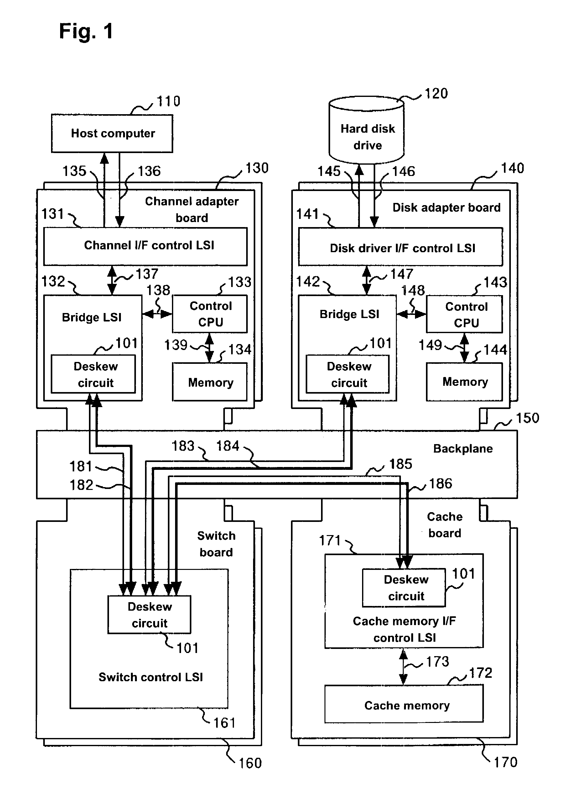
[0021] FIG. 1 is a block diagram of a disk array control device in accordance with one embodiment of the present invention. The disk array control device is formed from a plurality of channel adapter boards 130 that control interface with a host computer 110, a plurality of disk adapter boards 140 that control interface with a hard disk drive 120, a plurality of switch boards 160 that control switching of data transfers between boards, and a cache board 170 that controls interface with a cache memory that temporarily retains data. The disk array control device connects the switch boards 160 with the channel adapter boards 130, the switch boards 160 with the disk adapter boards 140, and the switch boards 160 with the cache board 170, each via a backplane 150 and with clock signals 181, 183 and 185, respectively, and command data buses 182, 184 and 186, r...


PUM

PropertyMeasurementUnit
transmission distanceaaaaaaaaaa
phasesaaaaaaaaaa
speedaaaaaaaaaa

Abstract

A deskew circuit includes, for clock and every bit of data, a variable delay circuit between a receiver that receives data and a flip-flop that first latches the data, in which a detecting pattern to detect a stable region for receiving data is repeatedly sent before implementing a data transfer, a delay value with which the starting edge and ending edge of the data match the rising edge of the clock is found for the variable delay circuit, and a delay value with which the transfer data can be received in a stable manner is set based on the delay value of the variable delay circuit.

Description

[0001] 1. Field of the Invention[0002] The present invention relates to a deskew circuit and a deskew method that corrects skews between clock and data, as well as among data on a data bus, in data transfers to transfer large volume data between packages at high-speed and to transfer clock and data in parallel.[0003] 2. Related Background Art[0004] A conventional technology that transmits data at high-speed while taking data skew into consideration has been indicated. In such a technology, a delay amount for every bit in data on the receiving side is adjusted using a phase adjustment pattern. However, phases are matched to an external clock supplied to both the transmitting and receiving sides, and the technology therefore is not a method to transfer clock and data in parallel.[0005] The conventional technology involves a method of adjusting only the clock in devices such as disk array control devices in which there is a large skew in a backplane due to the large number of packages ...

Claims


Application Information

Patent Timeline
Patent Type & Authority Applications(United States)
IPC IPC(8): G06F3/06G06F1/10G06F1/12G06F13/42G11B20/14H04L7/00
CPCG06F3/0601G06F2003/0692H04L7/0041H04L7/0337G11B20/14G06F3/0673
Inventor TAKEI, YUJIABE, SEIICHI
Owner HITACHI LTD
Why Eureka
Try Eureka