
Exhaust emission control system and method

a technology of exhaust gas emission control system and internal combustion engine, which is applied in the direction of electric control, machines/engines, mechanical equipment, etc., can solve the problems of nox storage/reduction catalyst degradation or deterioration, nox storage/reduction catalyst gradual reduction, and the ability to remove nox from exhaust gas. , to achieve the effect of reducing the nox removal capability of the nox storage/reduction catalyst, the effect of reducing the nox removal capacity

Active Publication Date: 2004-04-22
TOYOTA JIDOSHA KK
View PDF8 Cites 35 Cited by
  • Summary
  • Abstract
  • Description
  • Claims
  • Application Information

AI Technical Summary

Benefits of technology

The patent relates to an exhaust emission control system for internal combustion engines that purifies exhaust gas of NOx using a NOx storage / reduction catalyst. The system determines the degree of degradation of the catalyst by measuring the amount of NOx stored in the catalyst and the amount of NOx that passes through the catalyst without being trapped or stored. The system also includes a function or step of determining the degree of degradation of the catalyst. The technical effect of the patent is to provide a system that accurately determines when the NOx storage / reduction catalyst needs to be replaced or when the catalyst needs to be restored to its original state through a rich-spike operation.

Problems solved by technology

However, the NOx storage / reduction catalyst undergoes degradation or deterioration for various reasons, and its capability of removing NOx from exhaust gas is reduced due to the degradation.
However, the above-mentioned SOx stored in the NOx storage / reduction catalyst is not discharged from the catalyst through the rich-spike operation for reduction and removal of NOx, and therefore the amount of SOx stored in the NOx storage / reduction catalyst gradually increases as the engine keeps operating at a lean air / fuel ratio, resulting in so-called sulfur poisoning or S poisoning, which causes a gradual reduction in the NOx removal capability of the NOx storage / reduction catalyst.
In addition to the S poisoning, the NOx storage / reduction catalyst may degrade due to, for example, a long period of use or operations under a high-temperature environment, resulting in a reduction in the NOx storage capacity.
The NOx storage / reduction catalyst that has degraded for reasons other than S poisoning may not be recovered or restored to its original state, and the catalyst may need to be replaced by a new one in the case where such degradation occurs.
However, the SOx stored in the NOx storage / reduction catalyst is not discharged from the catalyst through a normal rich-spike operation, and therefore SOx remains in the catalyst even after rich spikes if the catalyst suffers from S poisoning, resulting in a reduction in the NOx storage capacity by a degree corresponding to the amount of SOx stored in the catalyst.
In the case where degradation of the catalyst occurs for other reasons than S poisoning, too, the NOx storage capacity is not completely restored even after rich spikes are executed.
Namely, once the NOx storage / reduction catalyst undergoes degradation, the NOx storage capacity of the catalyst is not completely restored even after rich spikes.
However, these systems fail to take account of the reliability of the output of the NOx sensor (or the detection accuracy of the sensor), thus giving rise to a possibility that false or inaccurate determinations are made on the degradation of the catalyst.
However, the detection accuracy of the NOx sensor is considerably reduced in a low concentration region, as described above, and therefore the reliability of the degradation determination itself is reduced if the degradation evaluation concentration is lowered.
Thus, the conventional emission control systems are not able to accurately determine degradation of the NOx storage / reduction catalyst, and may cause a problem that the exhaust NOx concentration exceeds the upper limit value under operating conditions in which the NOx emission amount of the engine is increased.
However, since the detection accuracy of the actual NOx sensor is considerably reduced in such a low concentration region, the NOx concentration cannot be detected with high accuracy in this region, and the degradation of the NOx storage / reduction catalyst cannot be determined with high accuracy.

Method used


Image

  • Exhaust emission control system and method
  • Exhaust emission control system and method
  • Exhaust emission control system and method

Examples


Embodiment Construction

[0050] An exemplary embodiment of the invention will be described with reference to the accompanying drawings.

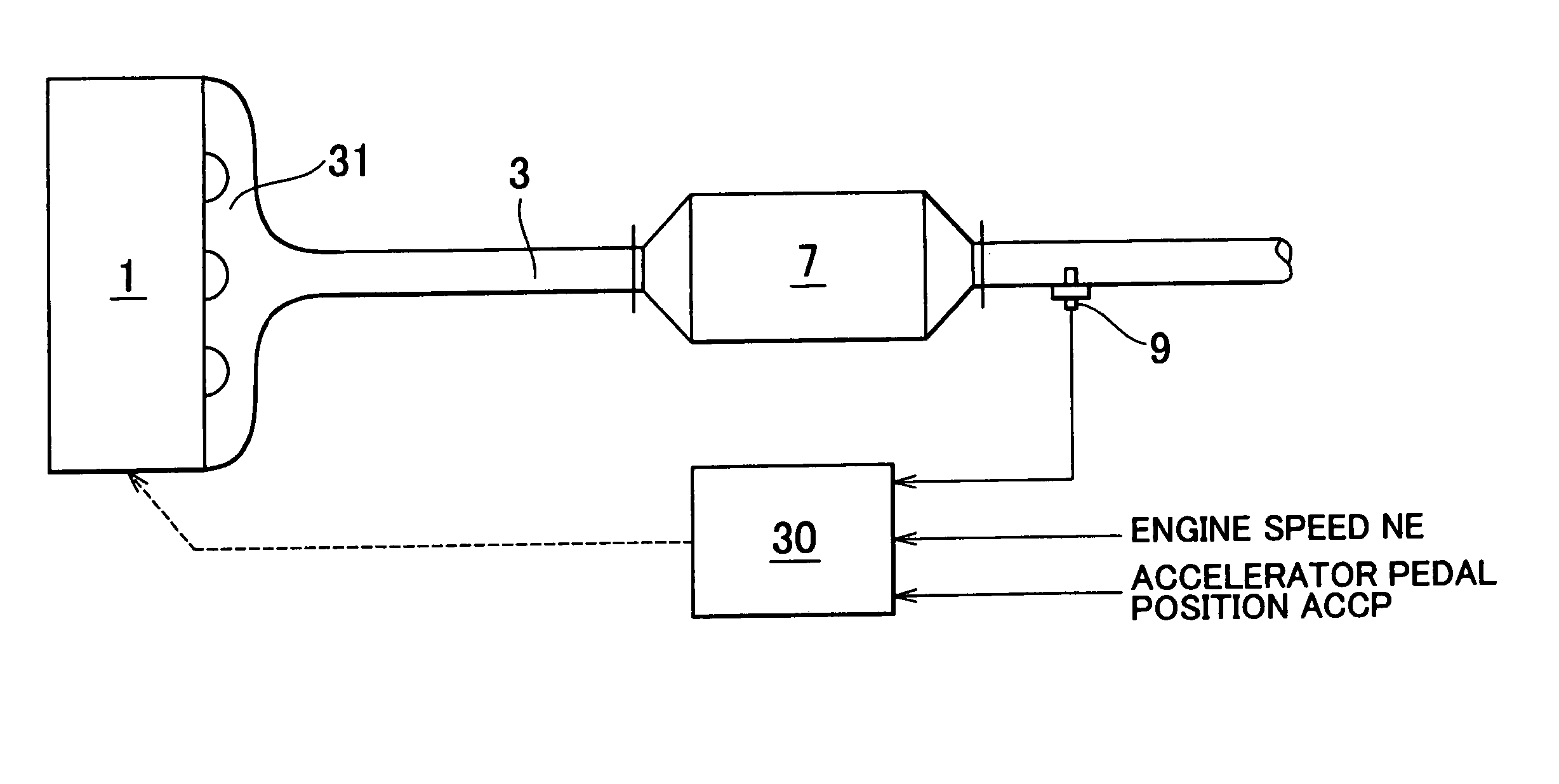
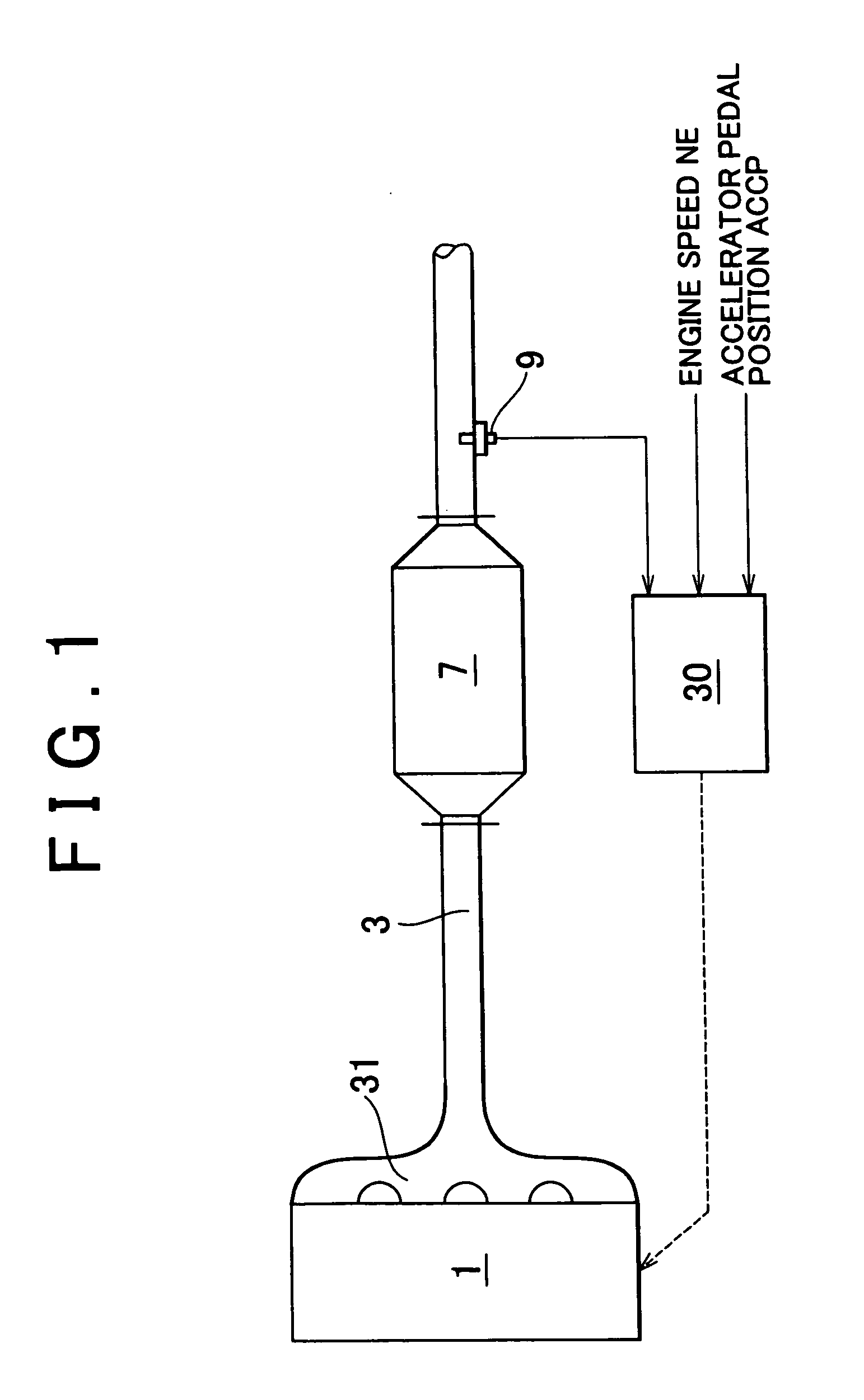
[0051] FIG. 1 schematically shows the construction of an exhaust emission control system as one exemplary embodiment of the invention when applied to an internal combustion engine of a vehicle, such as an automobile.

[0052] The system shown in FIG. 1 includes a main body of the internal combustion engine 1, an exhaust pipe 3 through which exhaust gas emitted by the engine 1 flows, and an exhaust manifold 31 that connects the exhaust pipe 3 to exhaust ports of respective cylinders of the engine 1.

[0053] In the present embodiment, a NOx storage / reduction catalyst 7 is disposed in the exhaust passage 3. The NOx storage / reduction catalyst 7 selectively traps and stores NOx contained in exhaust gas flowing into the catalyst, through adsorption or absorption or both processes, when the air / fuel ratio of the incoming exhaust gas is lean, and reduces and removes the stored NOx by usi...


PUM


Abstract

An exhaust emission control system for an internal combustion engine is provided which includes a NOx storage / reduction catalyst disposed in an exhaust passage of the engine, and a NOx sensor positioned in the exhaust passage downstream of the catalyst. A controller of the system performs a rich-spike operation to temporarily operate the engine at a rich air / fuel ratio each time a NOx storage state of the catalyst satisfies a predetermined rich-spike condition during a lean-burn operation. When the degree of degradation of the catalyst is determined by comparing the output of the NOx sensor with a predetermined evaluation value, the rich-spike condition is changed so that the amount of NOx stored in the catalyst at the time of a start of the rich-spike operation during a degradation determination period is made larger than that reached during a period other than the determination period.

Description

INCORPORATION BY REFERENCE[0001] The disclosure of Japanese Patent Application No. 2002-305879 filed on Oct. 21, 2002, including the specification, drawings and abstract, is incorporated herein by reference in its entirety.[0002] 1. Field of the Invention[0003] The invention relates generally to exhaust emission control system and method for an internal combustion engine, and, more particularly, to such exhaust emission control system and method that purify exhaust emissions by using a NOx storage / reduction catalyst, and have a function or step of determining the degree of degradation of the NOx storage / reduction catalyst. The NOx storage / reduction catalyst is adapted to selectively store NOx contained in exhaust gas, through adsorption, absorption or both of them, when the air / fuel ratio of the exhaust gas flowing into the catalyst is lean, and reduce and remove the stored NOx by using reducing components in the exhaust gas when the air / fuel ratio of the exhaust gas flowing into th...

Claims


Application Information

Patent Timeline
Patent Type & Authority Applications(United States)
IPC IPC(8): F02D45/00F01N3/08F01N3/20F01N3/24F01N3/28F01N11/00F02D41/02F02D41/04F02D41/14
CPCF01N3/0842F01N11/00F01N2550/03F01N2560/026F01N2570/14F01N2900/0422Y02T10/47F02D41/146F02D41/1495F02D2200/0404F02D2200/0811F02D2200/1002F02D41/0275Y02A50/20Y02T10/40
Inventor TANAKA, HIROSHI
Owner TOYOTA JIDOSHA KK
Learn More