Method for cleaning and sealing a well borehole portion for formation evaluation

a well borehole and well sealing technology, applied in the direction of sealing/packing, wellbore/well accessories, survey, etc., can solve the problems of contaminated sealing portion with return fluid, unmanageable pressure control within sealed portion, and existence of cuttings in return fluid

Inactive Publication Date: 2004-04-29
BAKER HUGHES INC
View PDF4 Cites 32 Cited by
  • Summary
  • Abstract
  • Description
  • Claims
  • Application Information

AI Technical Summary

Problems solved by technology

Whenever the sealing device fails to maintain a good seal, the sealed portion may become contaminated with return fluid or pressure control within the sealed portion becomes unmanageable due to pressure communication between the sealed portion and the rest of the annulus.
A common cause sealing problems is the existence of cuttings in the return fluid.
As a sealing device is moved to engage the borehole wall, cuttings or thick mud layers are trapped between the sea

Method used


Image

  • Method for cleaning and sealing a well borehole portion for formation evaluation
  • Method for cleaning and sealing a well borehole portion for formation evaluation
  • Method for cleaning and sealing a well borehole portion for formation evaluation

Examples


Embodiment Construction

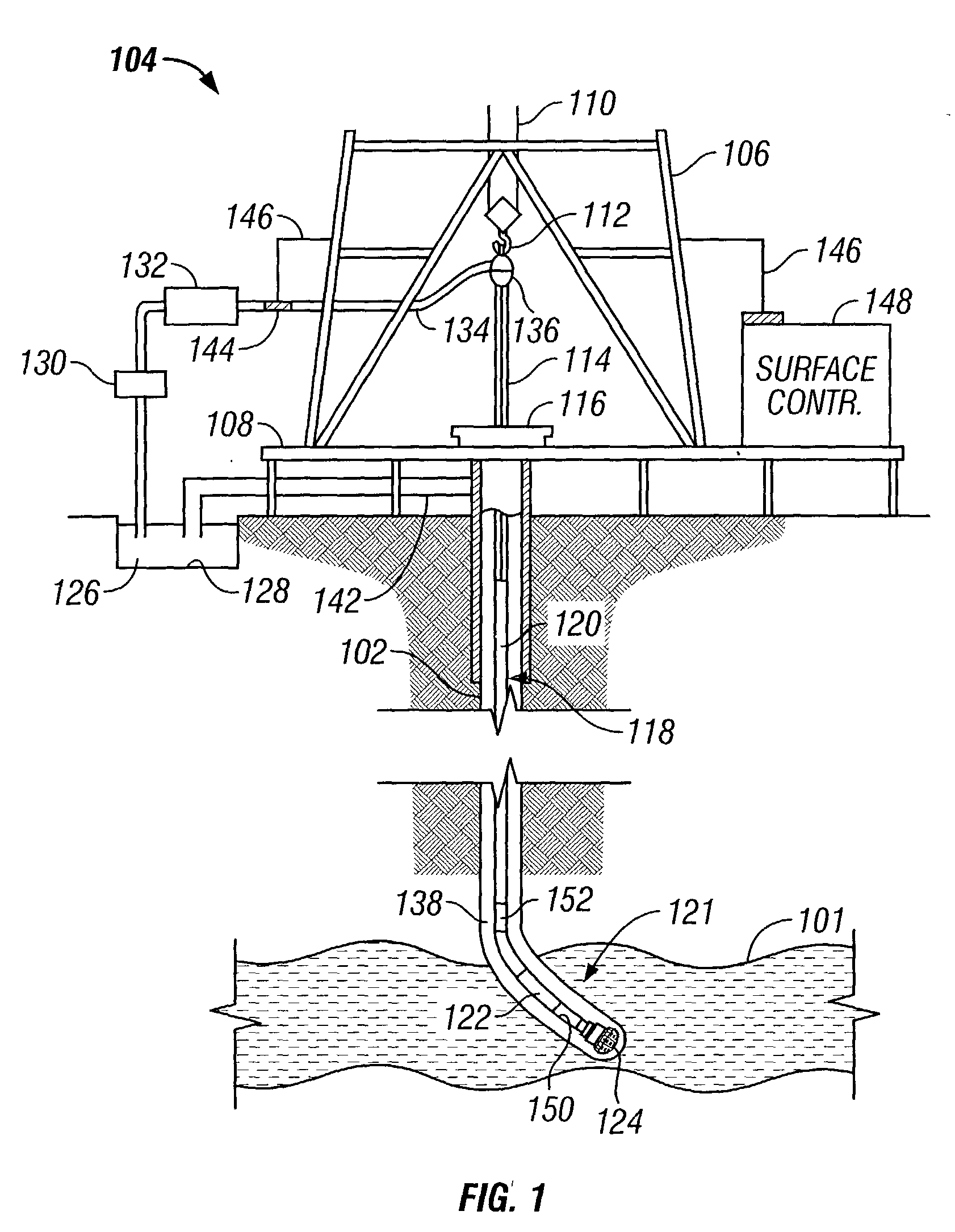
[0024] FIG. 1 is an elevation view of a simultaneous drilling and logging system that incorporates an embodiment of the present invention. A well borehole 102 is drilled into the earth under control of surface equipment including a rotary drilling rig 104. In accordance with a conventional arrangement, rig 104 includes a derrick 106, derrick floor 108, draw works 110, hook 112, kelly joint 114, rotary table 116, and drill string 118. The drill string 118 includes drill pipe 120 secured to the lower end of the kelly joint 114 and to the upper end of a section comprising a plurality of drill collars. The drill collars include not separately shown drill collars such as an upper drill collar, an intermediate sub drill collar, and a lower drill collar bottom hole assembly (BHA) 121 immediately below the intermediate sub. The lower end of the BHA 121 carries a downhole tool 122 of the present invention and a drill bit 124.

[0025] Clean drilling fluid 126 is circulated from a mud pit 128 th...


PUM


Abstract

A borehole wall cleaning apparatus and method for obtaining an improved seal between a fluid sampling device and a portion of the borehole wall. Clean drilling fluid is pumped into a drilling tool using a mud pump. A fluid diverter in the tool diverts all or part of the clean drilling fluid through a port to clear a portion of a borehole wall. A sealing pad is moved against the clean portion. A sampling port is exposed to the sealed portion for sampling and/or testing fluid from the formation.

Description

[0001] 1. Field of the Invention[0002] This invention generally relates to the testing of underground formations or reservoirs, and more particularly to an apparatus and method for effecting a cleaned and sealed well borehole wall portion for improved formation fluid sampling from a formation surrounding the wall portion.[0003] 2. Description of the Related Art[0004] Formation testing while drilling ("FTWD") is a form of formation evaluation that incorporates aspects of wireline logging into a drilling operation. Today, well boreholes are drilled by rotating a drill bit attached at a drill string end. The drill string may be a jointed rotatable pipe or a coiled tube. A large portion of the current drilling activity involves directional drilling, i.e., drilling boreholes deviated from vertical and / or horizontal boreholes, to increase the hydrocarbon production and / or to withdraw additional hydrocarbons from earth formations. Modern directional drilling systems generally employ a dril...

Claims


Application Information

Patent Timeline
IPC IPC(8): E21B37/00E21B49/10
CPCE21B49/10E21B37/00
Inventor MEISTER, MATTHIASHERBERG, WOLFGANGKRUEGER, SVEN
Owner BAKER HUGHES INC
Why Eureka
Try Eureka