Apparatus and methods for sampling and testing a formation fluid

a technology of formation fluid and apparatus, which is applied in the field of apparatus and methods for sampling and testing formation fluid, can solve the problems of significant amount of capital required for commercial development of hydrocarbon fields, difficulty in conveying wireline tools in deviated boreholes, and significant amount of time and money required for retrieving drill string and running a second test rig into the hol

Inactive Publication Date: 2004-05-27
BAKER HUGHES INC
View PDF4 Cites 65 Cited by
  • Summary
  • Abstract
  • Description
  • Claims
  • Application Information

AI Technical Summary

Problems solved by technology

Commercial development of hydrocarbon fields requires significant amounts of capital.
Although wireline conveyed tools are capable of testing a reservoir, it is difficult to convey a wireline tool in a deviated borehole.
Regardless of the type of test equipment currently used, and regardless of the type of communication system used, the amount of time and money required for retrieving the drill string and running a second test rig into the hole is significant.
Further, when a hole is highly deviated wireline conveyed test figures cannot be used because frictional force between the test rig and the wellbore exceed gravitational force causing the test rig to stop before reaching the desired formation.
A problem with the system described in the '186 patent relates to the time required for completing a test.
If formation pressure is lower than expected, the pressure from the mud column may cause unnecessary damage to the formation.
If the formation pressure is higher than expected, a pressure kick could result.
Consequently, delay in providing measured pressure information to the operator results in drilling mud being maintained at too high or too low a density for maximum efficiency and maximum safety.
A drawback of the '186 patent, as well as other systems requiring fluid intake, is that system clogging caused by debris in the fluid can seriously impede drilling operations.
If the system is clogged, it may have to be retrieved from the borehole for cleaning causing enormous delay in the drilling operation.
The pressure spike can cause damage to the formation.
In addition the pressure spike creates an erroneous start pressure for the draw down sequence of the test.

Method used


Image

  • Apparatus and methods for sampling and testing a formation fluid
  • Apparatus and methods for sampling and testing a formation fluid
  • Apparatus and methods for sampling and testing a formation fluid

Examples


Embodiment Construction

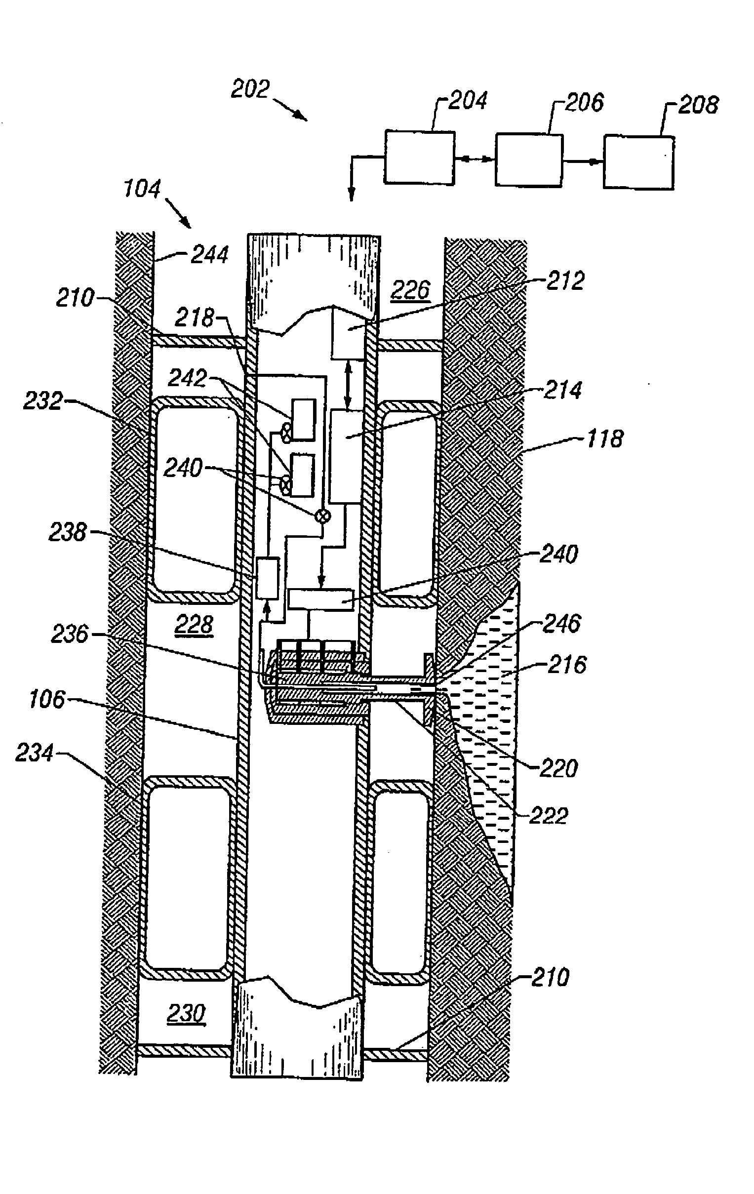
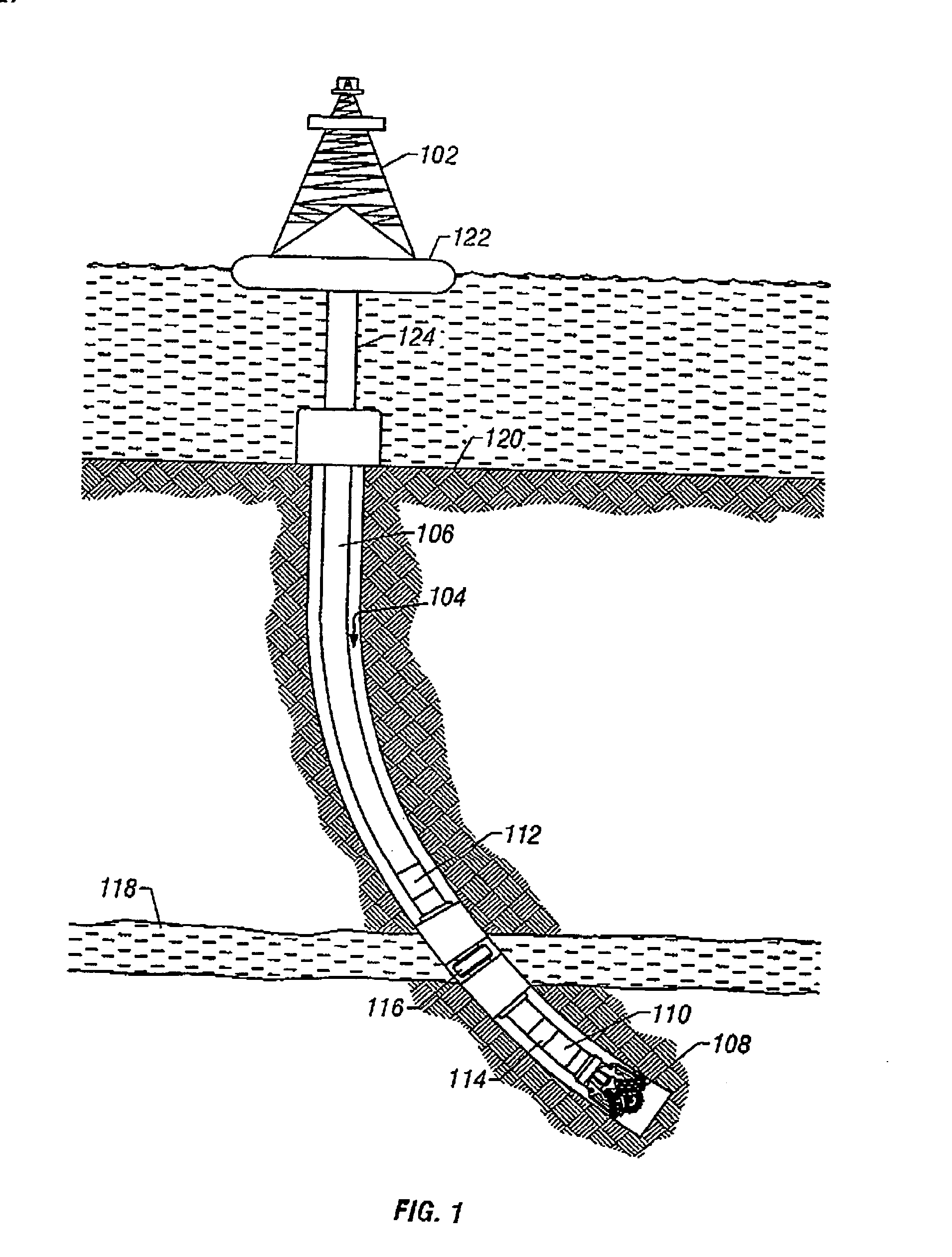
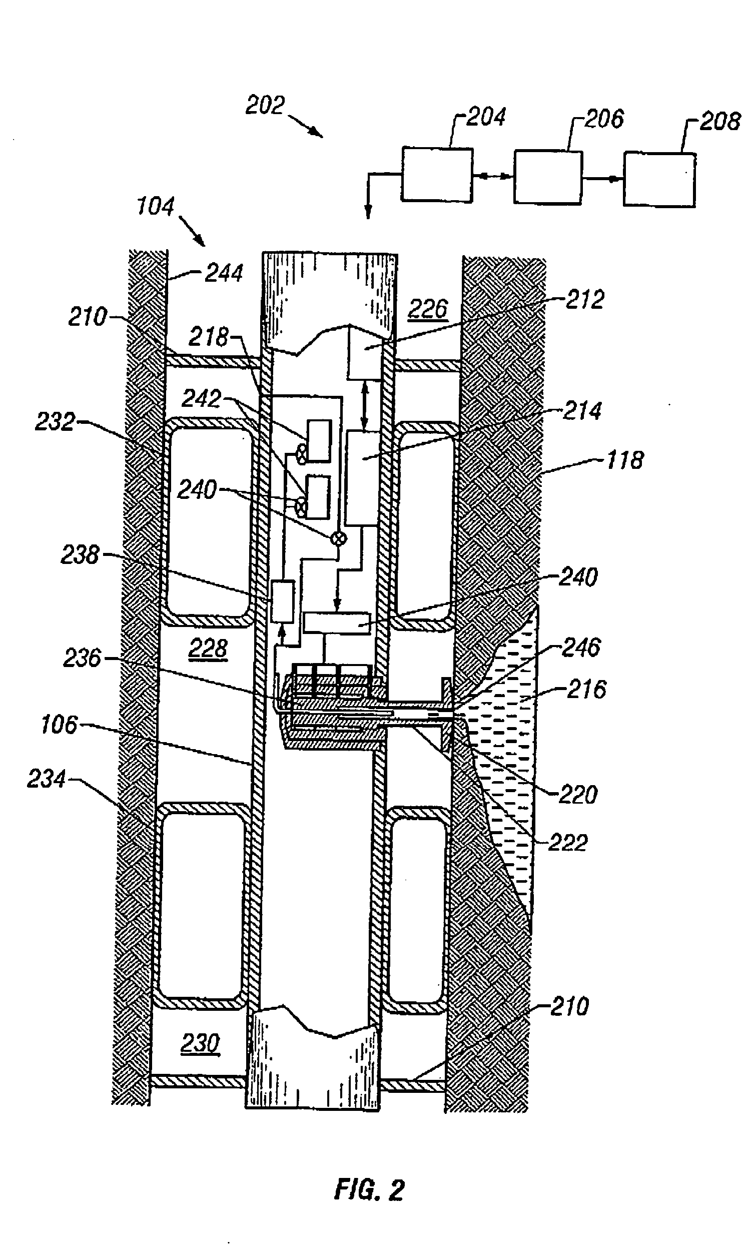
[0035] FIG. 1 is a typical drilling rig 102 with a borehole 104 being drilled into the subterranean formations 118, as is well understood by those of ordinary skill in the art. The drilling rig 102 has a drill string 106, which in the typical embodiment shown in FIG. 1 is a drill string. The work string 106 has attached thereto a drill bit 108 for drilling the borehole 104. The present invention is also useful in other types of work strings, and it is useful with jointed tubing as well as coiled tubing or other small diameter work string such as snubbing pipe. The drilling rig 102 is shown positioned on a drilling ship 122 with a riser 124 extending from the drilling ship 122 to the sea floor 120.

[0036] If applicable, the drill string 106 (or any suitable work string) can have a downhole drill motor 110 for rotating the drill bit 108. Incorporated in the drill string 106 above the drill bit 108 is at least one typical sensor 114 to sense downhole characteristics of the borehole, the...


PUM


Abstract

A formation test tool and methods are described that enable sampling and measurements of parameters of fluids contained in a borehole while reducing the time required for taking such samples and measurements and reducing the risk of formation damage due to sampling induced pressure spikes. The tool has a quick response control system for controlling a fluid transfer device in response to fluid pressure near a sampling port.

Description

[0001] The present application is a Continuation-in-Part of U.S. patent application Ser. No. 09 / 621,398 filed on Jul. 21, 2000, and is related to U.S. patent application Ser. No. 10 / 213,865 filed on Aug. 7, 2002, that is a Continuation of U.S. patent application Ser. No. 09 / 621,398.[0002] 1. Field of the Invention[0003] This invention generally relates to the testing of underground formations or reservoirs. More particularly, this invention relates to an apparatus and methods for sampling and testing a formation fluid.[0004] 2. Description of the Related Art[0005] To obtain hydrocarbons such as oil and gas, well boreholes are drilled by rotating a drill bit attached at a drill string end. The drill string may be a jointed rotatable pipe or a coiled tube. A large portion of the current drilling activity involves directional drilling, i.e., drilling boreholes deviated from vertical and / or horizontal boreholes, to increase the hydrocarbon production and / or to withdraw additional hydroc...

Claims


Application Information

Patent Timeline
Patent Type & Authority Applications(United States)
IPC IPC(8): E21B44/00E21B49/00E21B49/10
CPCE21B44/00E21B49/10E21B49/008
Inventor MEISTER, MATTHIASKRUEGER, SVEN
Owner BAKER HUGHES INC
Why Eureka
Try Eureka