

Exhaust gas recirculating device
a recirculating device and exhaust gas technology, applied in mechanical devices, machines/engines, lighting and heating apparatus, etc., can solve the problems of increasing the number of connection points, affecting the functioning of catalysts and the like, and unable to save spa
- Summary
- Abstract
- Description
- Claims
- Application Information
AI Technical Summary
Problems solved by technology
Method used
Image

Examples
embodiment 1
[0053] FIG. 3 is a cross sectional view to show the inner structure of an EGR device in accordance with embodiment 1 of the present invention. FIG. 4 is a perspective view of relevant part of the EGR device shown in FIG. 3 with parts partially broken away. FIG. 5 is a cross sectional view taken on line V - V in FIG. 3. FIG. 6 is a longitudinal cross sectional view, on an enlarged scale, to show relevant part of the EGR device shown in FIG. 3. In the drawings, reference numeral 100 denotes an EGR valve, 200 denotes an EGR cooler, 300 denotes a bypass pipe, and 400 denotes a bypass valve.
[0054] The EGR valve 100 has a substantially cylindrical housing 110 made of aluminum. A gas introducing port 111 for introducing exhaust gas into the housing 110 is formed in the bottom of housing 110. An exhaust gas discharging port 112 for discharging the exhaust gas into the EGR cooler 200 is formed in the side of housing 110. An exhaust gas discharging port 113 for discharging the exhaust gas int...
embodiment 2
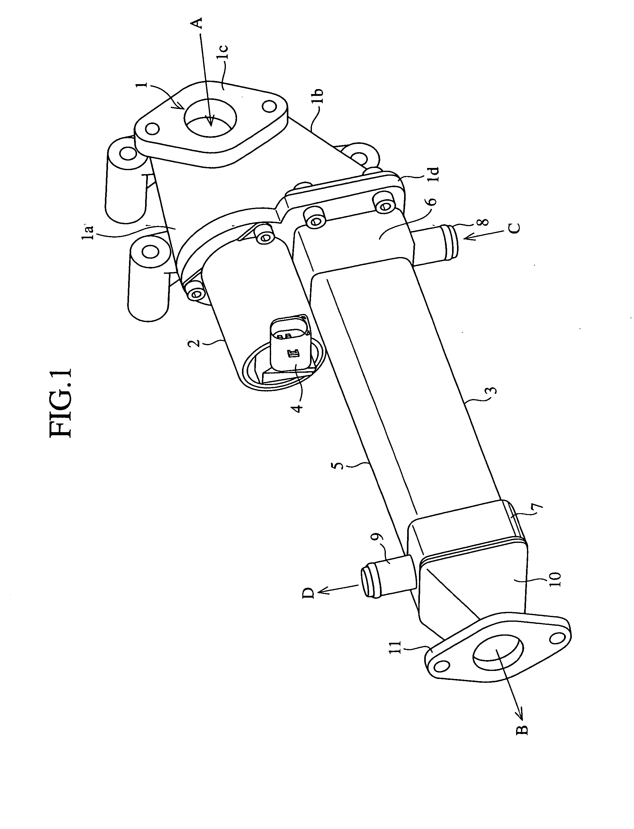
[0071] FIG. 7 is a perspective view to show the outer structure of the EGR device in accordance with embodiment 2 of the present invention. FIG. 8 is a front view to show the structure of piping of the EGR valve used in the EGR device shown in FIG. 7. FIG. 9 is a longitudinal cross sectional view, on an enlarged scale, to show relevant part of the EGR device shown in FIG. 7. FIG. 10 is a cross sectional view taken on line X - X in FIG. 9. Constituent elements of this embodiment 2 that are common to those of the embodiment 1 are denoted by the same reference symbols and their further descriptions will be omitted.
[0072] A feature of this embodiment 2 lies in that two exhaust gas discharging ports 112 and 113 which are parallel to each other, as shown in FIG. 7 and FIG. 8, are arranged in a direction orthogonal to the axial direction of EGR valve 100. For this reason, both of the exhaust gas discharging ports 112 and 113 are arranged near the actuator 190, so that the length of a valve...
embodiment 3
[0077] FIG. 11 is a transverse sectional view, on an enlarged scale, to show relevant part of the EGR device in accordance with embodiment 3 of the present invention. Constituent elements of this embodiment 3 that are common to those in the embodiment 1 and 2 are denoted by the same reference symbols and their further descriptions will be omitted.
[0078] A feature of this embodiment 3 is different from that of the embodiment 2 and lies in that the downstream end portion 205a of this pipe 205 is so configured as to be bent and slanted along the inner peripheral direction of case 201. The cooling water flowing into the cooling water passage 202 from the pipe 205 uniformly goes around in the case 201 as shown by arrows in FIG. 11. With this structure, the exhaust gas in the plurality of exhaust gas passages 250 can be cooled to a predetermined temperature.
[0079] As described above, according to this embodiment 3, the pipe 205 is configured such that its downstream end 205a is directed t...
PUM
 Abstract
Description
Claims
Application Information