Refrigeration cycle system

a technology of refrigerant cycle and cycle system, which is applied in the direction of indirect heat exchangers, transportation and packaging, light and heating equipment, etc., can solve the problems of not being able to actually expect greater improvement in the performance of cooling passenger compartments, and affecting the efficiency of refrigerant exchang

Inactive Publication Date: 2004-06-17
DENSO CORP
View PDF6 Cites 31 Cited by
  • Summary
  • Abstract
  • Description
  • Claims
  • Application Information

AI Technical Summary

Benefits of technology

[0014] In this case, the area of opening or the degree of throttle opening of the valve hole of the variable throttle valve or the amount of lift of the valve body can be reduced as the level of subcooling of the refrigerant delivered from the refrigerant-to-refrigerant heat exchanger increases, thereby decreasing the amount of the refrigerant circulating through the refrigeration cycle system. Accordingly, the degree of dryness or the level of superheating of refrigerant on the outlet side of the refrigerant evaporator is optimized and thus the performance of the refrigerant evaporator is improved.
[0025] On the other hand, when the level of subcooling of a refrigerant delivered from the first refrigerant conduit of the refrigerant-to-refrigerant heat exchanger and introduced into the valve hole of the variable throttle valve decreases and the internal pressure of the first pressure chamber is higher than the internal pressure of the second pressure chamber, the diaphragm is displaced to drivingly open the valve body against a biasing force of the valve body bias means. This allows the amount of the refrigerant circulating through the refrigeration cycle system to increase, thereby providing a lower level of superheating of the refrigerant on the outlet side of the refrigerant evaporator.

Problems solved by technology

This causes the air passing through the evaporator 105 to be cooled with an insufficient degree of efficiency, thereby raising the problem of being unable to actually expect greater improvement in the performance of cooling the passenger compartment.
This results in a larger amount of heat being exchanged in the refrigerant-to-refrigerant heat exchanger when compared with a saturated gaseous refrigerant.
On the other hand, for example, an insufficient amount of a refrigerant circulating through the refrigeration cycle system for its cooling load would cause an excessive level of superheating of the low pressure refrigerant delivered from the refrigerant evaporator and directed to the refrigerant compressor.
Furthermore, the system has no temperature-sensitive cylinder for sensing the level of superheating on the outlet side of the refrigerant evaporator.
More specifically, suppose that the amount of a refrigerant circulating through the refrigeration cycle is excessive for a cooling load.
On the other hand, suppose that the amount of a refrigerant circulating through the refrigeration cycle is insufficient for a cooling load.

Method used


Image

  • Refrigeration cycle system
  • Refrigeration cycle system
  • Refrigeration cycle system

Examples


Embodiment Construction

]

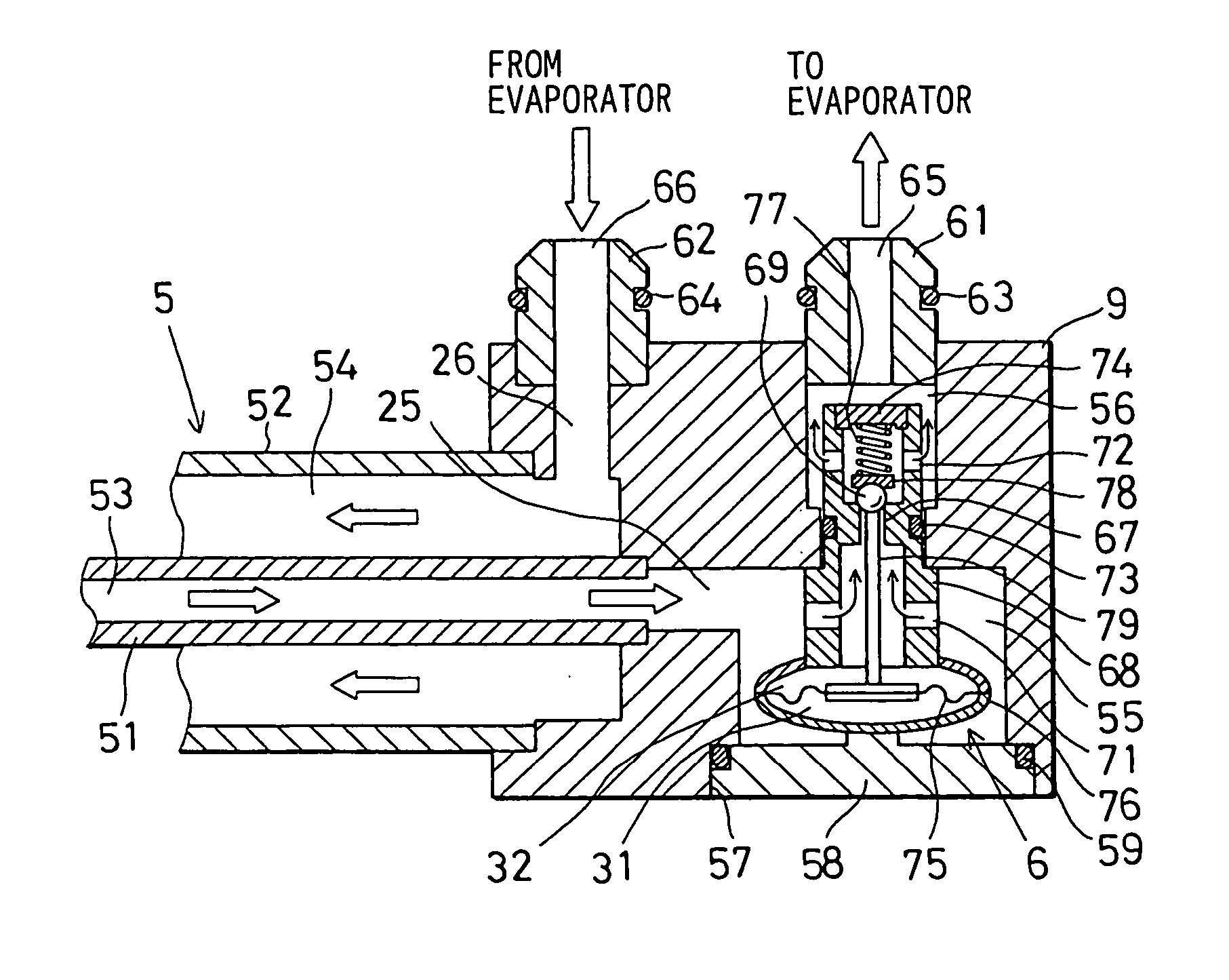
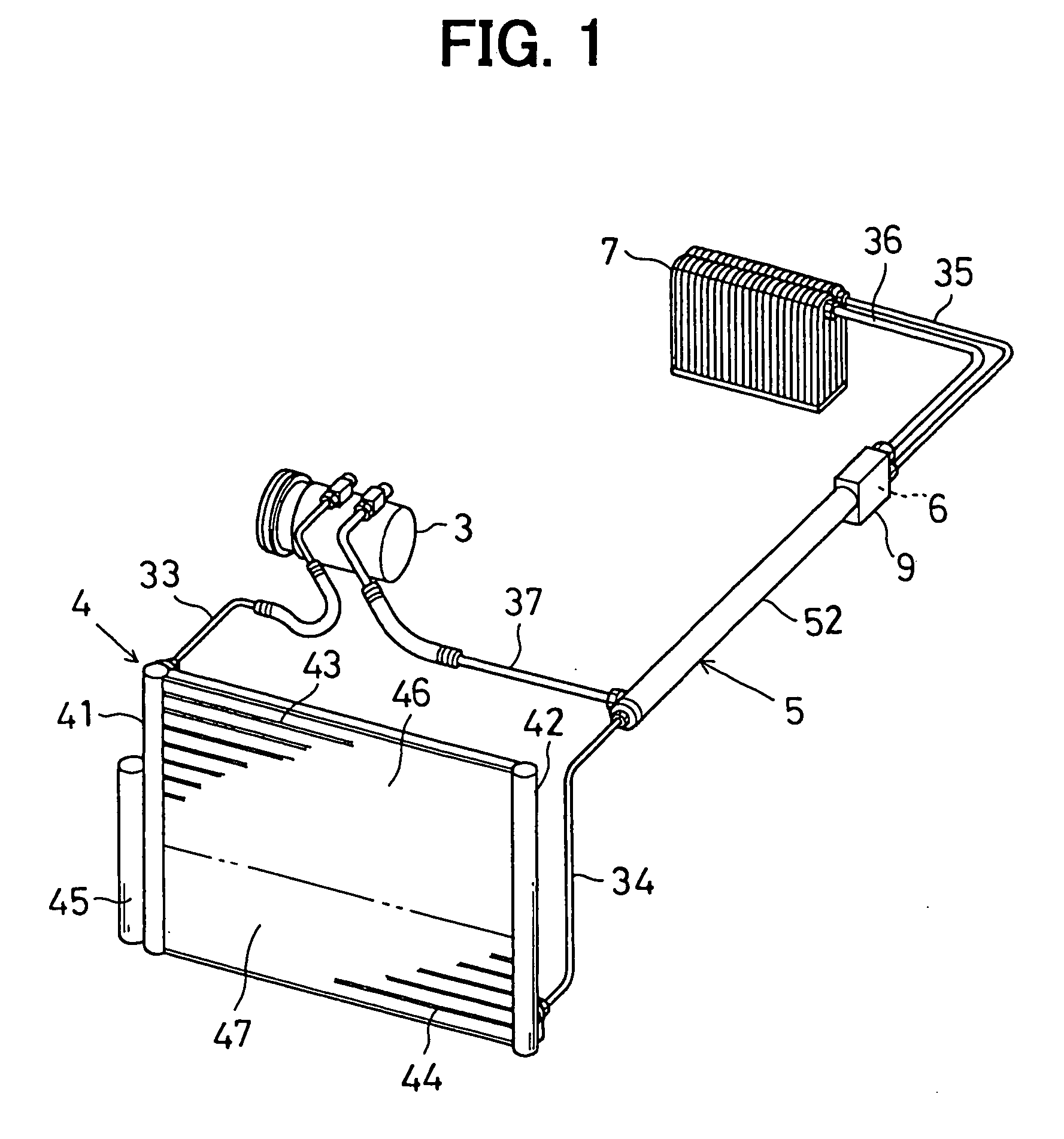
[0087] As described above, the refrigeration cycle of the vehicle air conditioning system according to this embodiment allows the double-pipe refrigerant-to-refrigerant heat exchanger 5 to exchange heat between the high pressure liquid refrigerant delivered from the subcooler 47 of the sub-cooling condenser 4 to the evaporator 7 and the low pressure, liquid and gas two phase refrigerant to be delivered from the evaporator 7 to the compressor 3. This especially allows the level of the superheating (SH) and the degree of dryness on the outlet side of the evaporator 7, among other things in the performance of the evaporator 7, to be fed back to the level of the subcooling (SC) upstream of the throttle hole 67 of the reverse sub-cooling control valve 6. That is, the amount of the refrigerant circulating through the refrigeration cycle is adjusted in response to the level of subcooling (SC), thereby making it possible to indirectly control the level of the superheating (SH) and the degr...


PUM


Abstract

A refrigeration cycle for a vehicle air conditioning system allows the refrigerant-to-refrigerant heat exchanger to exchange heat between a high-pressure liquid refrigerant, which is delivered from the sub-cooling condenser and directed to the evaporator, and a low-pressure refrigerant having a liquid and gas phase, which is delivered from the evaporator and directed to the compressor. The refrigeration cycle also allows the amount of the refrigerant circulating through the refrigeration cycle to be adjusted in response to the level of sub-cooling upstream of a throttle hole of a reverse sub-cooling control valve to thereby indirectly control the level of superheating on the outlet side of the evaporator. This provides improvements both in the amount of heat to be exchanged between refrigerants in the refrigerant-to-refrigerant heat exchanger and the cooling performance of the evaporator.

Description

[0001] This application is based upon, claims the benefit of priority of, and incorporates by reference Japanese Patent Application No. 2002-355835 filed Dec. 6, 2002.[0002] 1. Field of the Invention[0003] The present invention relates to a refrigeration cycle system with a refrigerant-to-refrigerant heat exchanger that allows heat exchange between a high-pressure refrigerant drawn from a liquid refrigerant receiver and directed to a variable throttle valve and a low-pressure refrigerant delivered from a refrigerant evaporator and directed to a refrigerant compressor. In particular, the present invention relates to a refrigeration cycle system which can control the amount of refrigerant in response to the level of subcooling of a refrigerant delivered from the refrigerant-to-refrigerant heat exchanger.[0004] 2. Description of the Related Art[0005] As shown in FIG. 10A, a conventionally known refrigeration cycle system has an annular refrigerant circuit through which a gaseous refrig...

Claims


Application Information

Patent Timeline
Patent Type & Authority Applications(United States)
IPC IPC(8): B60H1/00B60H1/32F25B1/00F25B40/00F25B41/06F28D7/00F28D7/10F28F9/02
CPCB60H1/00885B60H2001/00957F25B40/00F25B41/062F25B2341/063F25B2400/0403F28F27/02F25B2600/19F25B2600/2507F28D7/106F28D2021/0073F28F9/0253F25B2400/0411F25B41/335
Inventor ITO, SHIGEKITAKANO, YOSHIAKIHOTTA, TERUYUKIYAMANAKA, YASUSHI
Owner DENSO CORP
Why Eureka
Try Eureka