Single use syringe

Inactive Publication Date: 2004-06-17
OCCUPATIONAL & MEDICAL INNOVATIONS
View PDF1 Cites 40 Cited by
  • Summary
  • Abstract
  • Description
  • Claims
  • Application Information

AI Technical Summary

Benefits of technology

[0022] a plunger moveable along the syringe body, the plunger having a plunger body and a plunger head, the plunger head being formed with a concave portion which is adapted to extend about at least portion of the inner end of the body portion when the plunger head is pushed against the inner portion, the plunger additionally having sealing means to seal the plunger against the inside wall of the syringe body, the sealing means being attached to the plunger via a hinge means, a forward part of the plunger adapted for compressive engagement with the needle holder to provide a propelling force and for freeing the outer end of the body portion from sealing engagement with the opening, thereby allowing the needle holder to be shot back into the syringe body.
[0026] The plunger head is formed with a concave portion that typically extends into the plunger body. The concave portion may be formed integrally with the plunger head. As the concave portion is designed to split will break, the concave portion typically has a wall thickness that is less than the wall thickness of the remainder of the plunger body. Lines of weakness may be provided in the concave portion to facilitate controlled spitting or breaking.
[0027] The concave portion typically has a profile to substantially conform to the profile of the inner end of the needle holder to reduce or eliminate any "dead space" when the plunger is pushed forwardly against the end of the syringe barrel.
[0029] A hinge means may be provided between the sealing means and the plunger body. The hinge means may comprise a portion of reduced thickness. The hinge means may allow the sealing means and the plunger body to move towards or away from each other.

Problems solved by technology

One type of syringe that shoots the needle back into the syringe body is extremely complicated and has up to 16 parts that must be assembled to form the finished syringe.
This known syringe is also restricted to volumes of larger than 3 ml as the various parts cannot be made to fit smaller syringes.
Another disadvantage with known syringes of this type is the inability to easily and readily injection mould the various components.
In practice, it is found that such a barrel is extremely difficult to mould and is virtually impossible to injection mould.
Thus, this type of syringe cannot be manufactured cheaply.
One disadvantage with this design is that a standard needle cannot be used.
This type of syringe is of course fairly limited in use to circumstances where suction can be provided.
It is found that attempting to cut a cuttable member to release a spring-biased needle is not always reliable and does not always work.
This arrangement requires a needle having a special design (containing an enlargement), which means that conventional needles cannot be used.
This arrangement requires a sliding frictional grip to hold the two-part together which is considered quite risky and requires careful manufacture.
The use of an elongate body in a needle holder makes this arrangement difficult for use in small and confined spaces.
However, there does not appear to be a version where the needle is not always biased, or is not biased at all during the injection cycle.
The versions that use vacuum to suck back the needle have too many disadvantages to make them commercially versatile and acceptable.
Another disadvantage with many existing single use syringes, is that the mechanism required to shoot back the needle often has a portion protruding into the syringe barrel, and can result in incomplete expulsion of the liquid from the barrel and through the needle.
In other words, many existing single use syringes have a "dead space" where the syringe fluid can collect and where the fluid will not be properly expelled from the syringe.
This can result in incomplete or erroneous levels of fluid being injected into a person.
Another disadvantage with some of the spring biased shoot back needles, is that in practice, it is possible to reassemble the mechanism which means that the syringe and needle can be reused.
Clearly, a single use syringe should be manufactured in such a manner that it would be impossible to reuse the syringe.
Another disadvantage with single use syringes, and perhaps also with other types of syringes that contain needles is the risk of needle stick when removing the cap that protects the needle.

Method used


Image

  • Single use syringe
  • Single use syringe
  • Single use syringe

Examples


Embodiment Construction

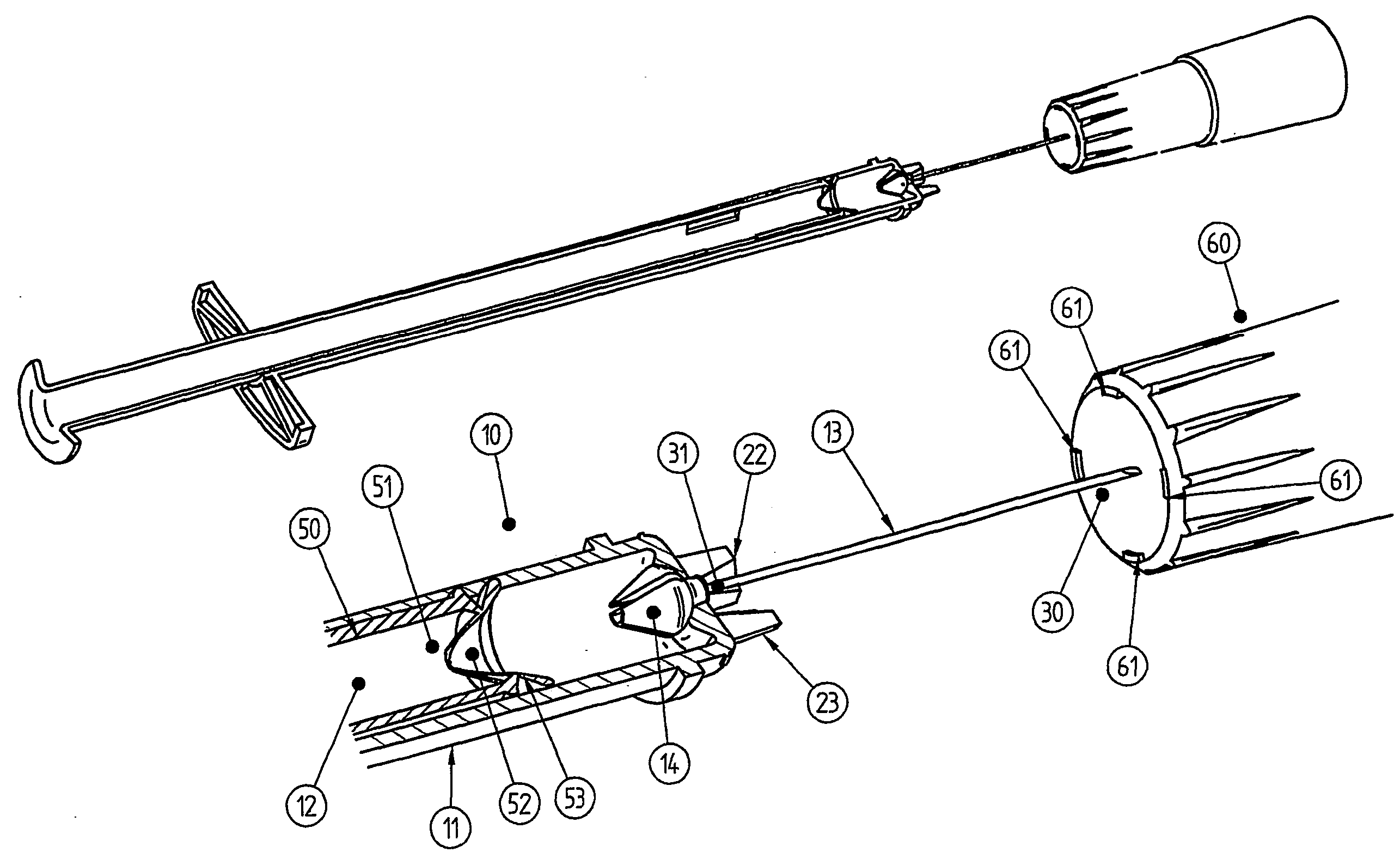
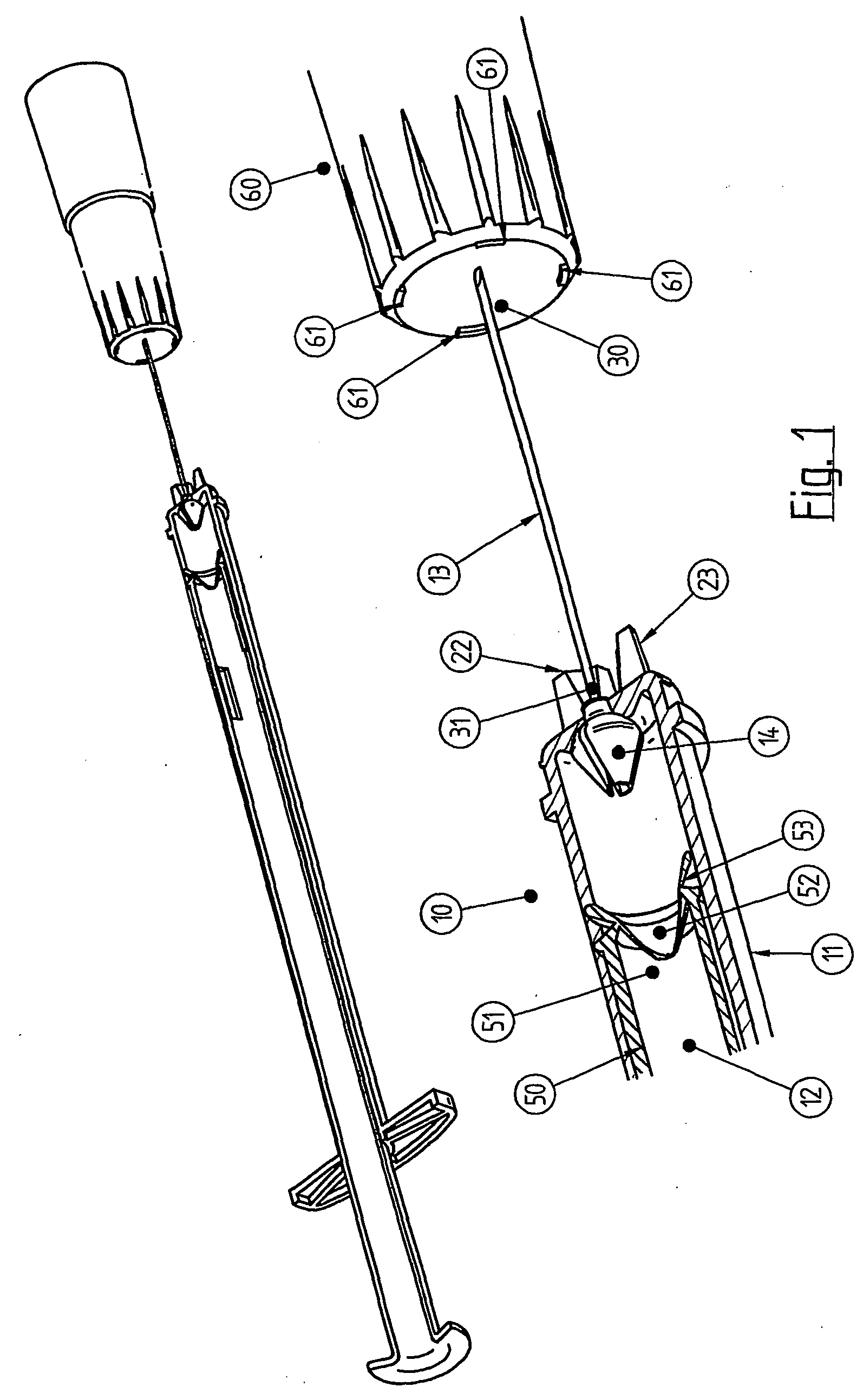
[0042] Referring to the drawings, and initially to FIG. 1, there is illustrated a single use syringe 10 which has a syringe body 11, a plunger 12 which slides along the syringe body, a needle 13 which can be of conventional design, and a needle holder 14.

[0043] Syringe 10 has an elongate syringe body as is known. The syringe body has a forward end portion 15 and a rearward end 16. The rearward end is open to allow the plunger to pass into and out of the syringe body. A radially extending flange 17 is attached to the rearward end 16 of the syringe body, as is known.

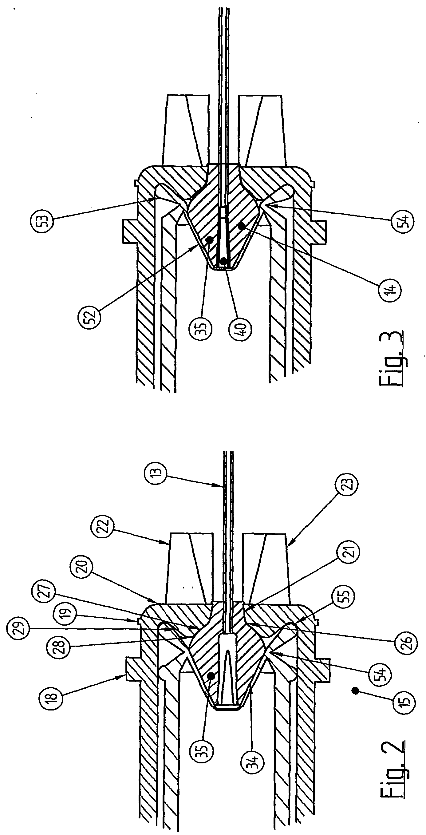
[0044] The syringe body differs from conventional syringes in the forward end portion 15. This is best illustrated in FIGS. 2-5. The forward end portion has a radially extending circumferential rib which functions to facilitate removal of the integrally formed cap 60 as will be described in greater detail below.

[0045] The forward end portion 15 has a front face 20. Front face 20 is provided with a more or less central open...


PUM


Abstract

A single use syringe uses a "pinching" action between a specially designed plunger and a specially designed needle holder to shoot the needle back into the syringe body upon completion of the piston stroke. The needle is not biased by a helical spring and the syringe remains in an unbiased condition until the plunger is pushed against the needle holder that creates the pinching action to shoot the needle back into the syringe body.

Description

[0001] This invention relates to a single use syringe of the type that has a needle that shoots back into the syringe body after use. The invention is particularly directed to various improvements to this type of syringe, including improvements to the shoot back mechanism. The shoot back mechanism need not require a helical spring, and the bias required to shoot back the syringe needle can be created by a combination of a specially configured plunger head pushing up against a specially configured needle holder. Thus, the bias required to shoot back the needle is formed or created just before use (i.e. when the plunger is fully pushed into the barrel), which means that when the plunger is in the retracted position, the needle is not biased. Conventional shoot back needle assemblies typically have the needle permanently biased.[0002] Single use syringes are required to reduce the risk of infection caused by needle sharing. Many types of single use syringes are known.[0003] One type of...

Claims


Application Information

Patent Timeline
IPC IPC(8): A61M5/158A61M5/32A61M5/50
CPCA61M5/3202A61M5/5086A61M5/508A61M5/3234
Inventor KIEHNE, BRUCE LEIGH
Owner OCCUPATIONAL & MEDICAL INNOVATIONS
Why Eureka
Try Eureka