
Ankle replacement system

a technology for replacing joints and bones, applied in the field of bones replacement systems, can solve the problems of limited use, increased stress on the knee and hip joints, and poor long-range prognosis for patients

Inactive Publication Date: 2004-06-17
INBONE TECH
View PDF15 Cites 10 Cited by
  • Summary
  • Abstract
  • Description
  • Claims
  • Application Information

AI Technical Summary

Problems solved by technology

Fusion, however, rendered the ankle stiff and generally immobile relative to the lower leg, resulting in limited use and additional stresses on the knee and hip joints.
Although these types of ankle replacements had some initial success in helping patients regain use of their ankle joint, the long range prognosis for patients has not been good.
Failures have been found in all models of total ankle replacement including the Mayo Clinic Total Ankle, the Oregon, and the Beck-Steffee models.
Approximately 61% of the replacements were reported as successful syndesmosis fusions, while the remaining cases evidenced various problems from delayed unions and nonunions which were often associated with the development of ballooning and circumferential lysis at the tibial component.
However, the tibiofibular syndesmosis is a large contributing factor in loosening and ballooning osteolysis problems encountered with the AGILITY.TM. Ankle.
This contributes to aseptic loosening and migration of the device.
Furthermore, although more recent replacements have attempted to alleviate stress from the tibia and talus by incorporating a fibular component and infusing tibiofibular syndesmosis, they still face common problems of prosthesis migration and loosening, and osteolysis at the tibial component.
Such surgical procedures require making large incisions at the ankle, moving the tendons and other soft tissue aside, and separating the tibia and fibula from the talus--essentially detaching the foot from the leg--to install the device, subsequently requiring complicated realignment and reattachment of the foot.
These procedures commonly result in infection and extended healing time with possible replacement failure from improper realignment.
The surgery also has increased risks associated with cutting or damaging neighboring nerves and tendons which may lead to further complications.

Method used


Image

  • Ankle replacement system
  • Ankle replacement system
  • Ankle replacement system

Examples


Embodiment Construction

System

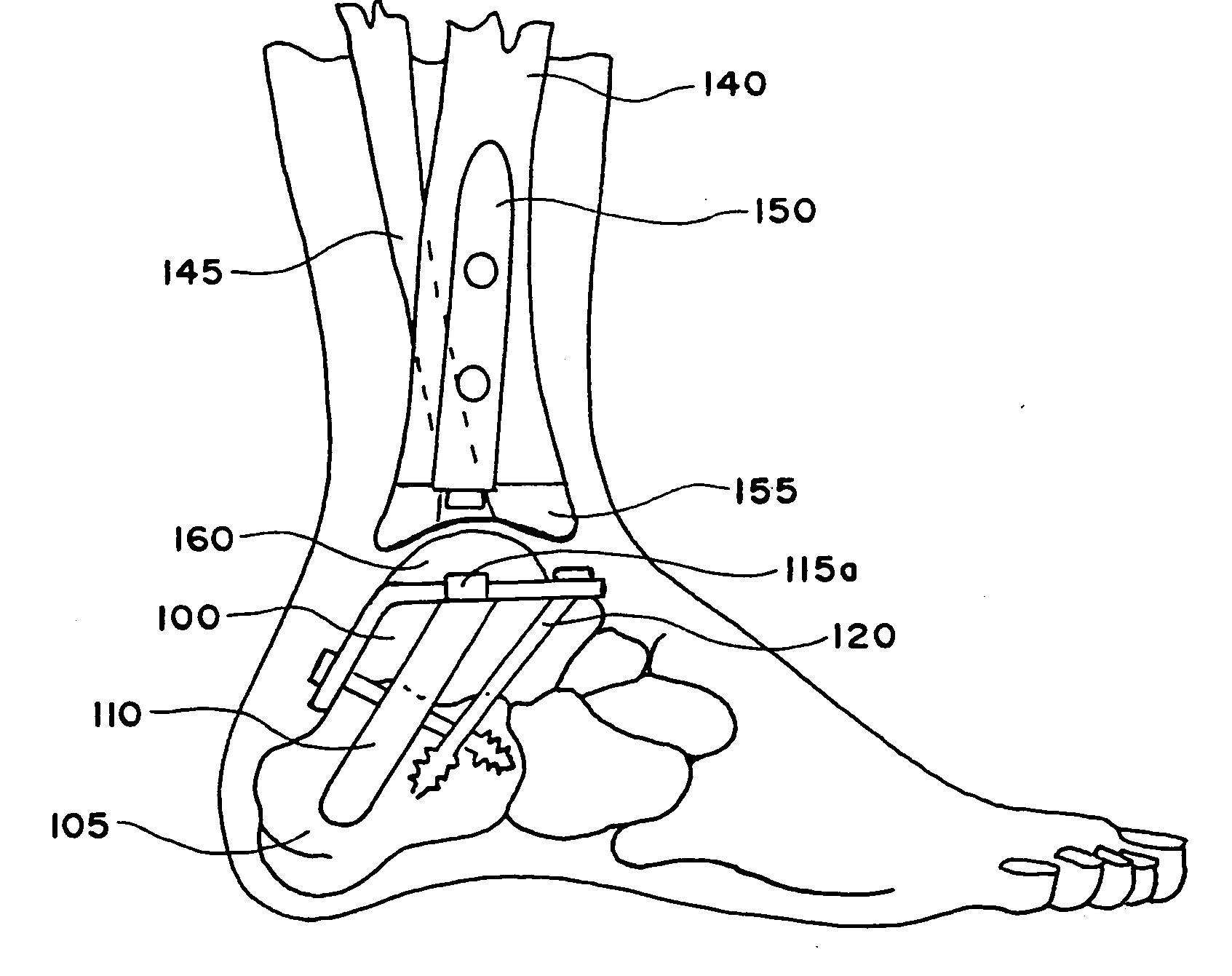
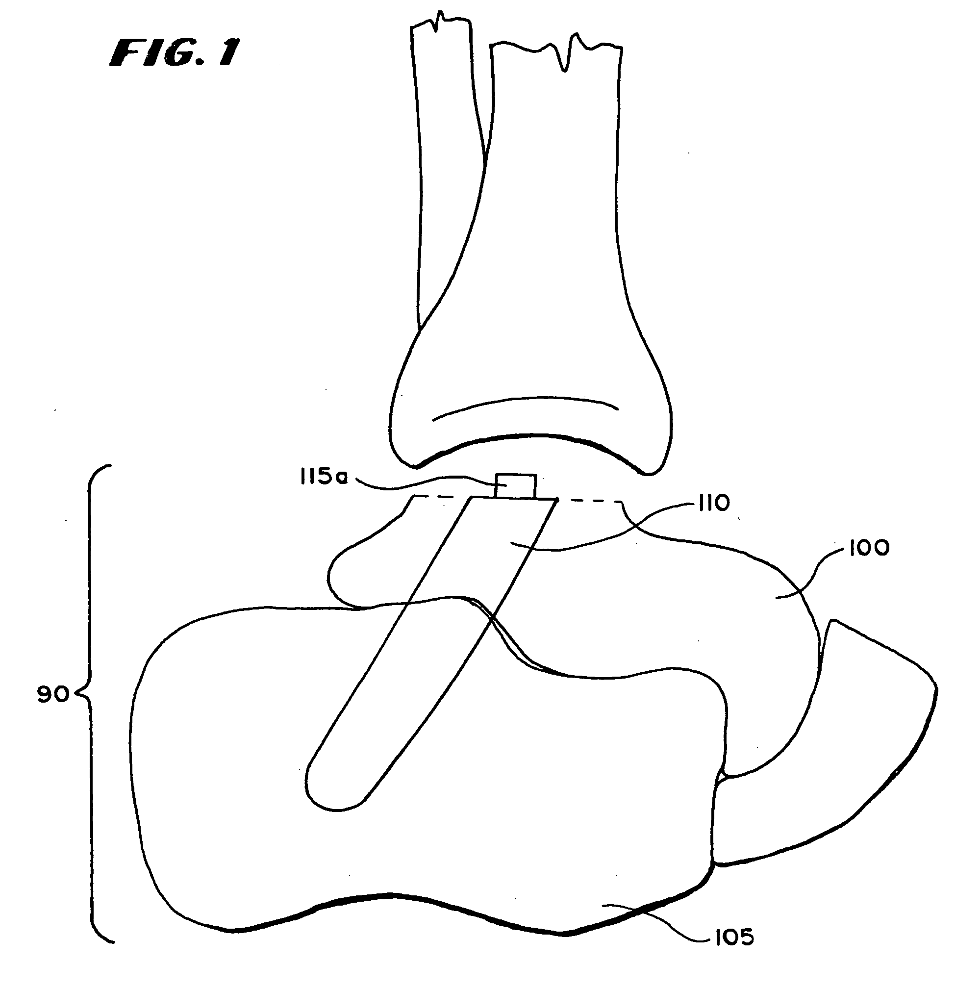
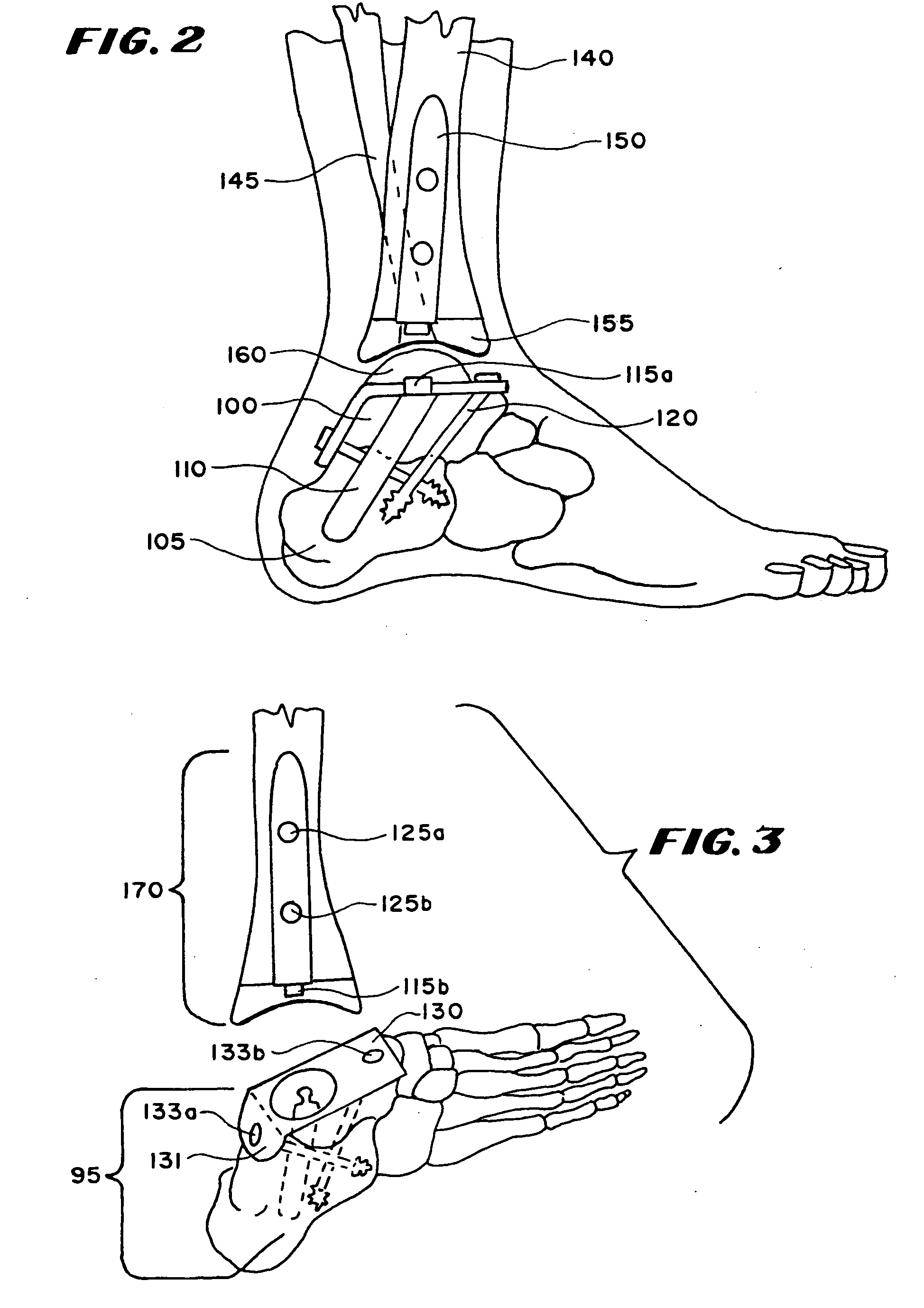
[0035] As embodied and broadly described herein, the present invention is directed to a novel system and method for Total Ankle Replacement (TAR). The ankle replacement system of the present invention includes a lower prosthesis body desirably fixed to the calcaneus and / or the talus, which greatly increases the amount of bone available for fixation as compared with conventional TAR systems, which traditionally included only the talus in fixation of a lower prosthesis. The enlarged available bone base allows fixation of larger talar trays or other prosthetic bases to provide greater prosthesis stability, and allows for anchoring of the lower prosthesis body with, for example, screws. This design provides greater stability and stress absorption for the prosthetic ankle joint, and decreases the probability of prosthesis loosening and subsidence.

[0036] In one embodiment of the present invention, the subtalar joint is fused to allow fixation of the lower prosthesis body to both the...


PUM

PropertyMeasurementUnit
lengthaaaaaaaaaa
lengthaaaaaaaaaa
lengthaaaaaaaaaa

Abstract

A total ankle replacement system, novel surgical method for total ankle replacement, and novel surgical tools for performing the surgical method are described. The total ankle replacement system includes the calcaneus in fixation of a lower prosthesis body, thereby significantly increasing the amount of bone available for fixation of the lower prosthesis body and allowing the lower prosthesis body to be anchored with screws. The total ankle replacement system further includes a long tibial stem which can also be anchored into the tibia with, for example, screws, nails, anchors, or some other means of attachment. The novel surgical arthroscopic method allows introduction of ankle prostheses into the ankle joint through an exposure in the tibial tubercle. Various novel surgical instruments, such as a telescoping articulating reamer and a talo-calcaneal jig, which facilitate the novel surgical method, are also described.

Description

[0001] This application is a divisional of co-pending U.S. patent application Ser. No. 09 / 694,100 filed 20 Oct. 2000 which claims the benefit of U.S. Provisional Patent Application Serial No. 60 / 160,892, filed Oct. 22, 1999, and entitled "Ankle Replacement Systems," which is incorporated herein by reference.[0002] 1. Field of the Invention[0003] The invention relates to ankle replacement systems including designs, methods and apparatus that reduce and / or prevent problems associated with subsidence, loosening, and late infection, in part, by incorporating a novel surgical procedure for replacing an ankle, at least in part, through a tibial tubercle exposure. The present invention is also directed to novel surgical instruments useful for performing an ankle replacement procedure.[0004] 2. Description of the Background[0005] Until the early to mid 1970's, patients with injured or diseased ankle joints commonly resulting from rheumatism, or degenerative or traumatic arthritis, had few o...

Claims


Application Information

Patent Timeline
Patent Type & Authority Applications(United States)
IPC IPC(8): A61B17/15A61B17/16A61B17/17A61B17/86A61F2/00A61F2/30A61F2/42A61F2/46
CPCA61B17/15A61F2/4606A61B17/1682A61B17/1717A61B17/8625A61F2/30767A61F2/4202A61F2002/30064A61F2002/30332A61F2002/30578A61F2002/30604A61F2002/30616A61F2002/30622A61F2002/30785A61F2002/30878A61F2002/30948A61F2002/30968A61F2002/4205A61F2002/4207A61F2002/421A61F2002/4631A61F2220/0033A61F2310/00017A61F2310/00023A61F2310/00029A61F2310/00131A61F2310/00179A61F2310/00329A61F2310/00395A61F2310/00796A61F2310/0097A61B2017/1775A61B17/1617A61B17/1775
Inventor REILEY, MARK A.
Owner INBONE TECH
Learn More