Exercise machine

a technology of exercise machine and stroke length, which is applied in the field of exercise machines, can solve the problems of cumbersome and expensive shipping of exercise machines to customers, not necessarily desirable characteristics, and inability to easily transport machines, so as to minimize frictional energy loss, reduce labor intensity, and reduce labor intensity

Inactive Publication Date: 2004-07-15
GREENHOUSE INT
View PDF23 Cites 13 Cited by
  • Summary
  • Abstract
  • Description
  • Claims
  • Application Information

AI Technical Summary

Benefits of technology

0015] The exercise machine may include a first mechanical advantage system connected to the resistance assembly whereby movement of the first handle by a first distance causes corresponding movement of at least a first part of the resistance assembly by a second distance which is smaller than the first distance. With this embodiment the resistance assembly may include first and second ends and, when the at least first part of the assembly is caused to move by the first handle, the first end engages with a first support on the frame and the second end moves relatively to the frame.
0016] The exercise machine may include a second mechanical advantage system connected to the resistance assembly whereby movement of the second handle by a third distance causes corresponding movement of at least a second part of the resistance assembly by a fourth distance which is smaller than the third distance.
0017] According to a different aspect of the invention there is provided an exercise machine which includes a frame, a resistance assembly supported by the frame, a first actuator which is movable by a user from a first rest position against a first resistance force which is dependent at least on the resistance assembly, to cause movement of at least a first part of the resistance assembly, the first actuator including at least a first device which is movable by the user and a first mechanical advantage system connected to the resistance assembly whereby movement of the first device by a first distance causes corresponding movement of the at least first part of the resistance assembly by a second distance which is smaller than the first distance, a second actuator which is movable by the user from a second rest position against a second resistance force which is dependent at least on the resistance assembly, to cause movement of at least a second part of the resistance assembly, the second actuator including at least a second device which is movable by the user and a second mechanical advantage system connected to the resistance assembly whereby movement of the second device by a third distance causes corresponding movement of the at least second part of the resistance assembly by a fourth distance which is smaller than the third distance.
0018] The first mechanical advantage system may, in a relatively simple form, comprise a cable and pulley system. The system may be designed so that movement of the first actuator through the first distance is greater than the corresponding resulting movement of the resistance assembly through the second distance. The mechanical advantage, in this respect, may be of the order of 2:1 but, preferably, is of the order of 4:1. Other ratios are possible. This feature carries with it the benefit that the stroke length is materially increased compared to the distance by which the resistance assembly is caused to move. The second mechanical advantage system may be similar in nature.
0019] It is important however to minimize frictional energy losses, particularly in a cable or pulley system. Thus the number of pulleys in the system should be restricted, where possible.
0020] The aforementioned arrangement means that it is possible to reduce the size of the exercise machine whilst maintaining a substantial stroke length. In order for the stroke length to take place against a fairly high resistance force it is necessary however for the resistance assembly to exhibit a substantial resistance force for, with a mechanical advantage of the order of 4, the force which is exerted on the first actuator is about a quarter of the resistance force.

Problems solved by technology

This is not necessarily a desirable characteristic.
When a user who is physically strong makes use of the exercise machine then the number of weights which must be provided is substantial and this carries with it a penalty in that the exercise machine is then not necessarily easily transportable and, inevitably, the exercise machine is cumbersome and expensive to ship to a customer.

Method used


Image

  • Exercise machine
  • Exercise machine
  • Exercise machine

Examples


Embodiment Construction

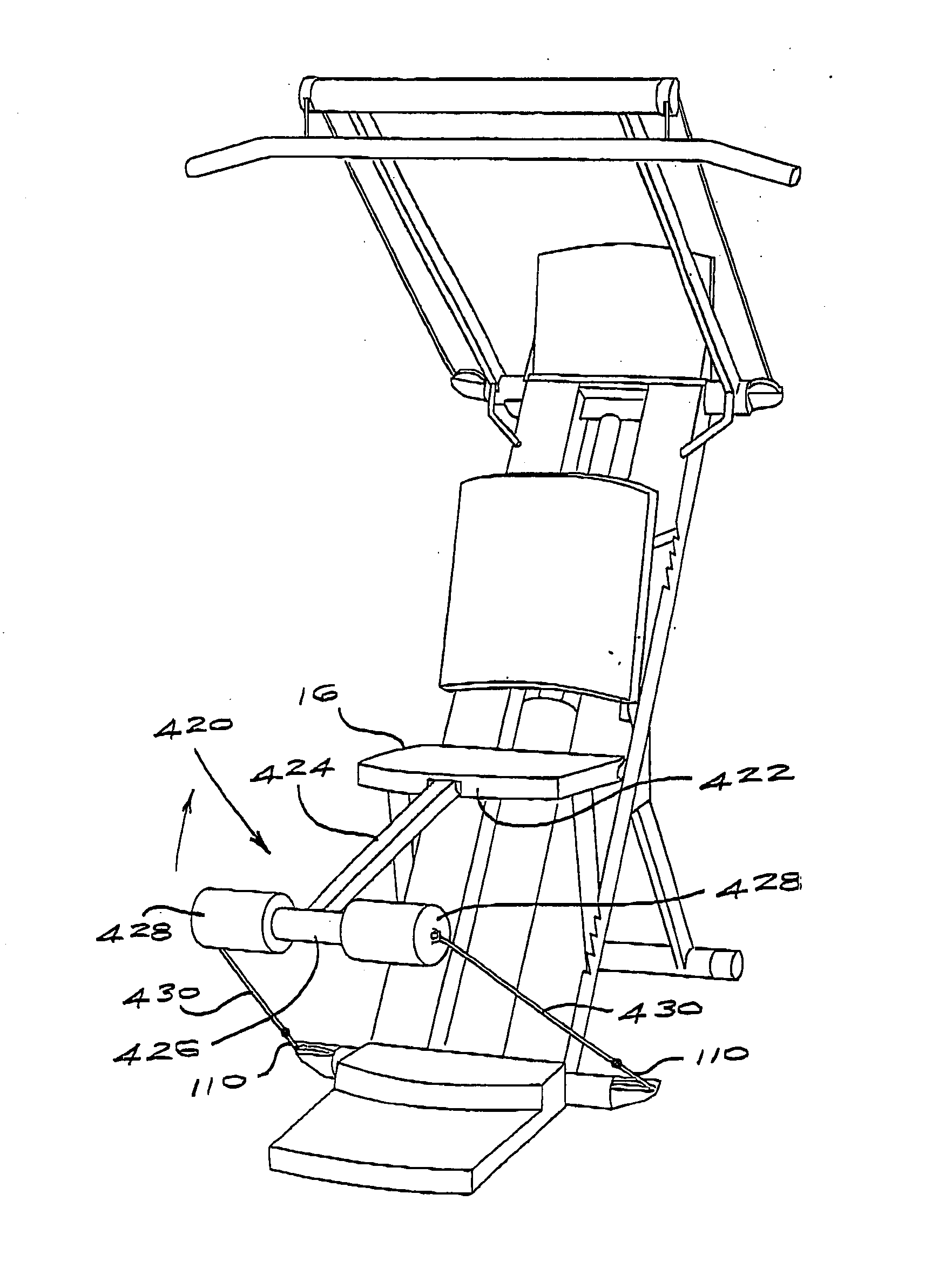
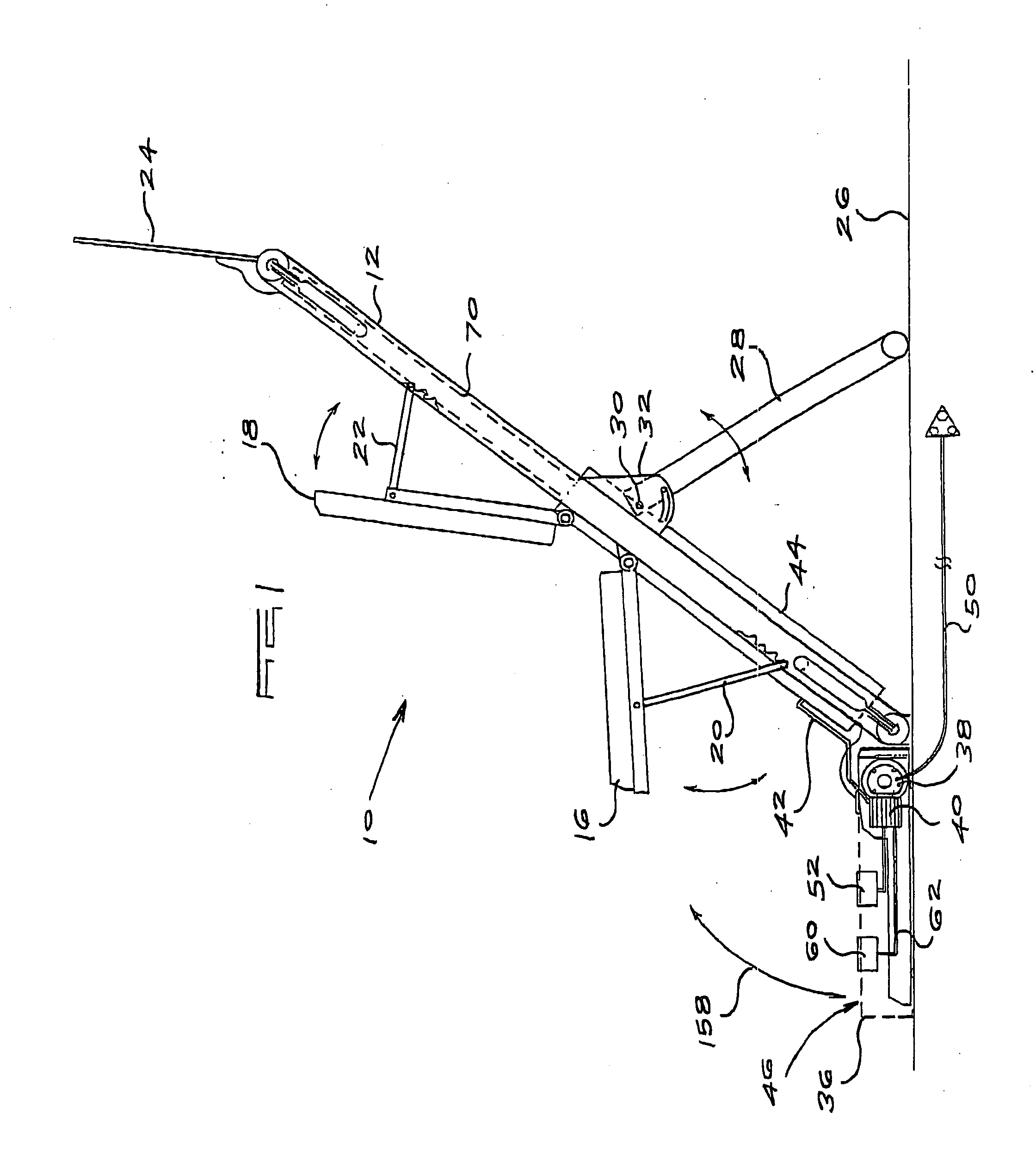
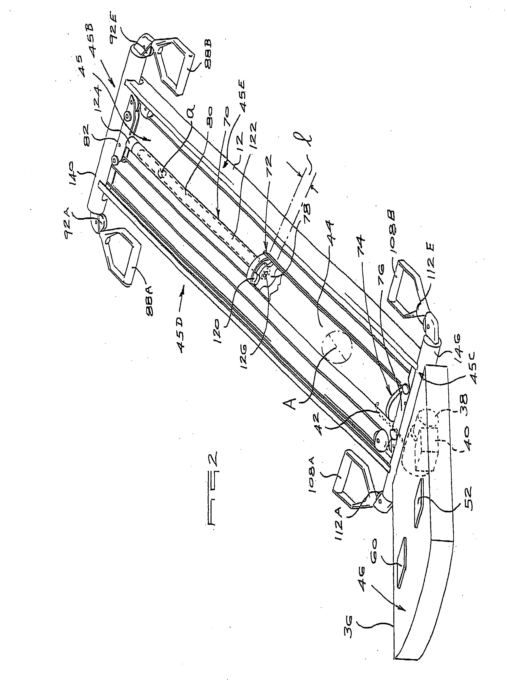
[0045] FIGS. 1 to 3 of the accompanying drawings illustrate an exercise machine 10 according to a first form of the invention.

[0046] The exercise machine includes an elongate frame 12 to which is attached a seat 16 on which a user can be seated, and a backrest 18 for the back of a user positioned on the seat. For storage and transport purposes the seat 16, which is normally braced by one or more stays 20, can be folded downwardly so that it is substantially parallel to the frame while, in a similar fashion, the backrest 18 which is braced by one or more stays 22 can be pivoted towards the frame to take up a compact position. A structure 24 can be used at an upper end of the frame as an holder for a card which carries information on exercise sequences.

[0047] The frame is supported at an inclined position relatively to the ground 26 by a downwardly depending U-member 28 which is attached at a pivot point 30 to brackets 32 on a rear side of the frame 12. The U-member 28 can be moved in...


PUM


Abstract

An exercise machine which includes an elongate frame which forms an enclosure, a resistance assembly located at least partly in the enclosure, a support member for supporting the frame at an inclined position with an upwardly facing front side and a downwardly facing rear side, a seat extending from the front side of the frame at a location at which part of the frame opposes a back of a user seated on the seat, and at least a first actuator which is movable by the user against a first resistance force which is generated by the resistance assembly.

Description

[0001] This invention relates to an exercise machine.[0002] Exercise machines make use of diverse devices such as free weights, weight plates, elastic bands, springs and the like to provide a resistance force against which a user can exercise. It has been found that, in many of these machines, the stroke length, which is the distance against which a user moves his arms or legs, as the case may be, against a resistive force, must be reasonably long and this, in turn, means that an exercise machine must also be of substantial dimensions.[0003] It is preferable to have a substantially constant resistance force, against which a user exercises, over the stroke length. If use is made of a spring or similar component, to provide the resistance force then, as is known, the spring characteristic is such that the resistance force increases more or less linearly with spring deformation. In other words the more the resistance device is moved the greater is the resistance force which acts agains...

Claims


Application Information

Patent Timeline
Patent Type & Authority Applications(United States)
IPC IPC(8): A63B21/00A63B21/008A63B21/04A63B21/055
CPCA63B21/00065A63B21/0087A63B21/04A63B21/0428A63B21/0552A63B21/0557A63B21/00069A63B21/156A63B2208/0228A63B2208/0233A63B2210/50A63B21/1484A63B21/154A63B21/4043
Inventor VAN STRAATEN, WILLEM JOHANNESPUZEY, MICHAEL ROYDON
Owner GREENHOUSE INT
Why Eureka
Try Eureka