Electronic circuit with asynchronous clocking of peripheral units

a technology of asynchronous clocking and peripheral units, applied in the field of electronic circuits, can solve the problems of imposing additional circuit effort on the controller design, reducing the design flexibility of the controller, and reducing the production cost of a mass produ

Inactive Publication Date: 2004-07-15
INFINEON TECH AG
View PDF6 Cites 21 Cited by
  • Summary
  • Abstract
  • Description
  • Claims
  • Application Information

AI Technical Summary

Problems solved by technology

Thus it would, for example, be unacceptable for a user to have to wait several minutes for an authentification check or a payment transaction.
In the usage of cryptography controllers in chip cards, such as, for example, SIM cards or signature cards, an additional problem arises from the fact that they have to be produced cheaply as a mass product.
In addition only a restricted amount of energy is available to cryptography controllers so that an additional restriction regarding the circuit effort is thus imposed on the controller design.
Consequently the computing speed of the coprocessors is restricted on the one hand by the production cost and on the other hand by the energy available.
A further problem in the design of cryptography controllers arises from the coexistence of many generally conventional cryptography algorithms.
Due to the versatile use, such a multifunctional cryptography controller, however, must be able to perform a variety of computing operations being used by the many cryptographical algorithms, which leads to an increase in complexity or a reduction of the speed of the electronic circuit.
Although the cryptography controller of FIG. 6, by providing several coprocessors 920a and 920b, is suitable for performing various tasks, such as various encrypting algorithms, and for performing computing operations in parallel, one problem of this arrangement is that the entire circuit 900 is clocked by a single external clock signal 1000 and that the PLL 990 consequently is only provided as a clock multiplier for the entire chip 900.
In the design of a chip 900 in CMOS technology, the problem is additionally aggravated by the fact that the power consumption in this case depends on the clock frequency or the switching frequency of the MOSFETs, respectively.
A disadvantage of the circuit 901 of FIG. 7 is that the coprocessors 920a and 920b can only be clocked synchronously by a certain multiple of the clock of the PLL 990.

Method used


Image

  • Electronic circuit with asynchronous clocking of peripheral units
  • Electronic circuit with asynchronous clocking of peripheral units
  • Electronic circuit with asynchronous clocking of peripheral units

Examples


Embodiment Construction

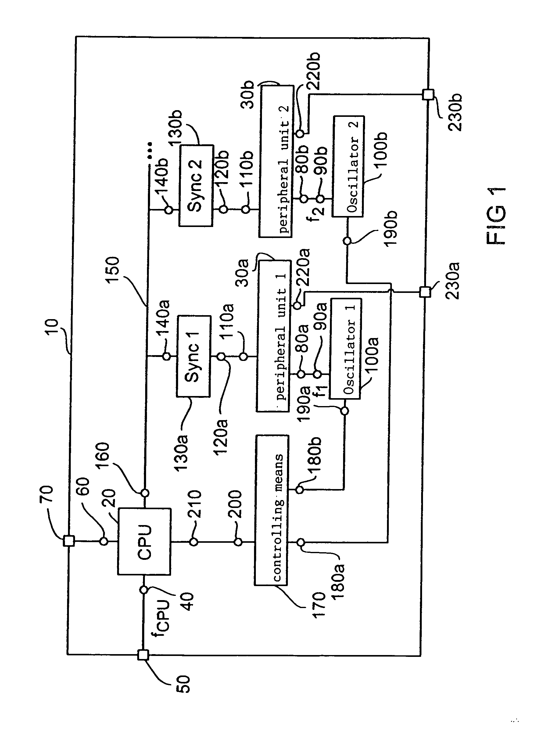
[0032] Referring to FIG. 1 the architecture of a cryptography controller according to an embodiment of the present invention is described at first. The cryptography controller 10 is integrated into an individual chip and includes a CPU 20 and a plurality of peripheral units 30a and 30b (in FIG. 1 only two of them are shown). The CPU 20 is connected to a connection device 50 via a clock connection 40 and to a connection device 70 of the chip 10 via a data connection 60. While the CPU 20 is fed with a clock frequency f.sub.CPU via the clock connection 40, the peripheral units 30a and 30b are connected to a signal output 90a, 90b of controllable oscillators 100a and 100b via a clock connection 80a, 80b to be fed by same with a clock of the frequency f.sub.1 or f.sub.1, respectively. A data connection 110a and 110b of the peripheral unit 30a and 30b is connected to a first data connection 120a or 120b, respectively, of a synchronization means 130a or 130b, respectively, for a clock sync...


PUM


Abstract

An inventive electronic circuit includes central processing means having a clock connection and a data connection, as well as a peripheral unit having a clock connection and a data connection, the clock connection of the peripheral unit being connected to a signal output of a controllable oscillator or to an external clock input. Synchronization means having a first and a second data connection is connected, the first data connection being connected to the data connection of the peripheral unit. In addition a data bus connects the data connection of the CPU and the second data connection of the synchronization means. The clocking of the peripheral unit asynchronous to the central processing unit yields a more effective operation being better adjustable to certain parameters, such as, for example, the application and the energy of the electronic circuit available.

Description

[0001] 1. Field of the Invention[0002] The present invention relates to electronic circuits and in particular to electronic circuits in which a central processing unit (CPU) and at least a peripheral unit are used, as is, for example, the case in cryptography controllers.[0003] 2. Description of Prior Art[0004] With the increasing use of cashless money transfer, electronic data transmission via public networks and the exchange of credit card numbers via public networks, the demand for cryptography algorithms increases to be able to perform digital signatures, authentifications or encrypting tasks. Well-known cryptography algorithms include asymmetrical encrypting algorithms, such as, for example, the RSA algorithm or processes basing on elliptical curves, or symmetrical encrypting processes, such as, for example, encrypting processes according to the DES or AES standards.[0005] In order to be able to perform the computations specified by the cryptography algorithms with an acceptabl...

Claims


Application Information

Patent Timeline
Patent Type & Authority Applications(United States)
IPC IPC(8): G06F1/08G06F1/12G06F1/32G06F13/40G06K19/07G06K19/073H04L9/10
CPCG06F1/08G06F1/12G06K19/073G06F13/405G06F1/3203
Inventor ELBE, ASTRIDJANSSEN, NORBERTSEDLAK, HOLGER
Owner INFINEON TECH AG
Why Eureka
Try Eureka