Brush motor

Inactive Publication Date: 2004-07-22
FUNAI ELECTRIC CO LTD
View PDF6 Cites 11 Cited by
  • Summary
  • Abstract
  • Description
  • Claims
  • Application Information

AI Technical Summary

Benefits of technology

[0013] The invention has been devised to overcome the above-described problems, and its object is to provide a brush motor which makes it possible to generate FG signal without making the shape large and the structure complex, which makes it possible to increase the output level of a magnetic sensor for generating the FG signal, and which facilitates the mounting of the magnetic sensor even when the output level is increased.
[0014] Another object of the invention is to provide a brush motor which makes it possible to generate the FG signal without making the shape large and the structure complex, by detecting a change in a field magnet which occurs in correspondence with a change in a rotational position of a rotor core by using the magnetic sensor.
[0015] Still another object of the invention is to provide a brush motor which makes it possible to increase the output level of the magnetic sensor by setting the circumferentially attaching position of the magnetic sensor in the vicinity of a central position of a magnetic pole of an annular permanent magnet.
[0016] A further object of the invention is to provide a brush motor which makes it possible to further increase the output level of the magnetic sensor by causing the permanent magnet to jut out from an axial end face of the rotor core on a side where the commutator is fitted, and by setting the attaching position of the magnetic sensor on an inner peripheral side of the jutting-out portion.
[0017] A still further object of the invention is to provide a brush motor which makes it possible to make the magnetic sensor inexpensive by using a coil as the magnetic sensor.
[0018] To solve the above-described problems, in accordance with the invention there is provided a brush motor comprising: a stator having a permanent magnet for forming a field magnet; a rotor in which rotor windings are wound around a rotor core; feeding brushes; a commutator through which a current is supplied to the rotor windings, the commutator sliding on the feeding brushes; and a Hall element provided for detecting a change in the field magnet occurring in correspondence with a change in the rotational position of the rotor core, wherein the permanent magnet is formed into an annular shape whose inner peripheral surface opposes an outer peripheral surface of the rotor core, a circumferentially attaching position of the Hall element is set in the vicinity of a central position of a magnetic pole of the permanent magnet, an axial length of the permanent magnet is set to be longer than that of the rotor core, the permanent magnet is made to jut out from an axial end face of the rotor core on a side where the commutator is disposed, and the attaching position of the Hall element is set on an inner peripheral side of the jutting-out portion.

Problems solved by technology

For this reason, in the case where the first prior art is used, a problem has occurred in that the structure of the motor becomes complex.
With the second prior art as well, since a separately provided rotating magnet is required for constructing the FG, problems have occurred in that the structure of the motor becomes complex, and that the shape becomes large in size.
In addition, the third prior art is a technique which is limited to a motor having a coreless armature.
However, in this case as well, the portion of the height of the Hall element and the portion of the width of the substrate 93 cause hindrances in flattering the shape of the apparatus.)

Method used


Image

  • Brush motor
  • Brush motor
  • Brush motor

Examples


first embodiment

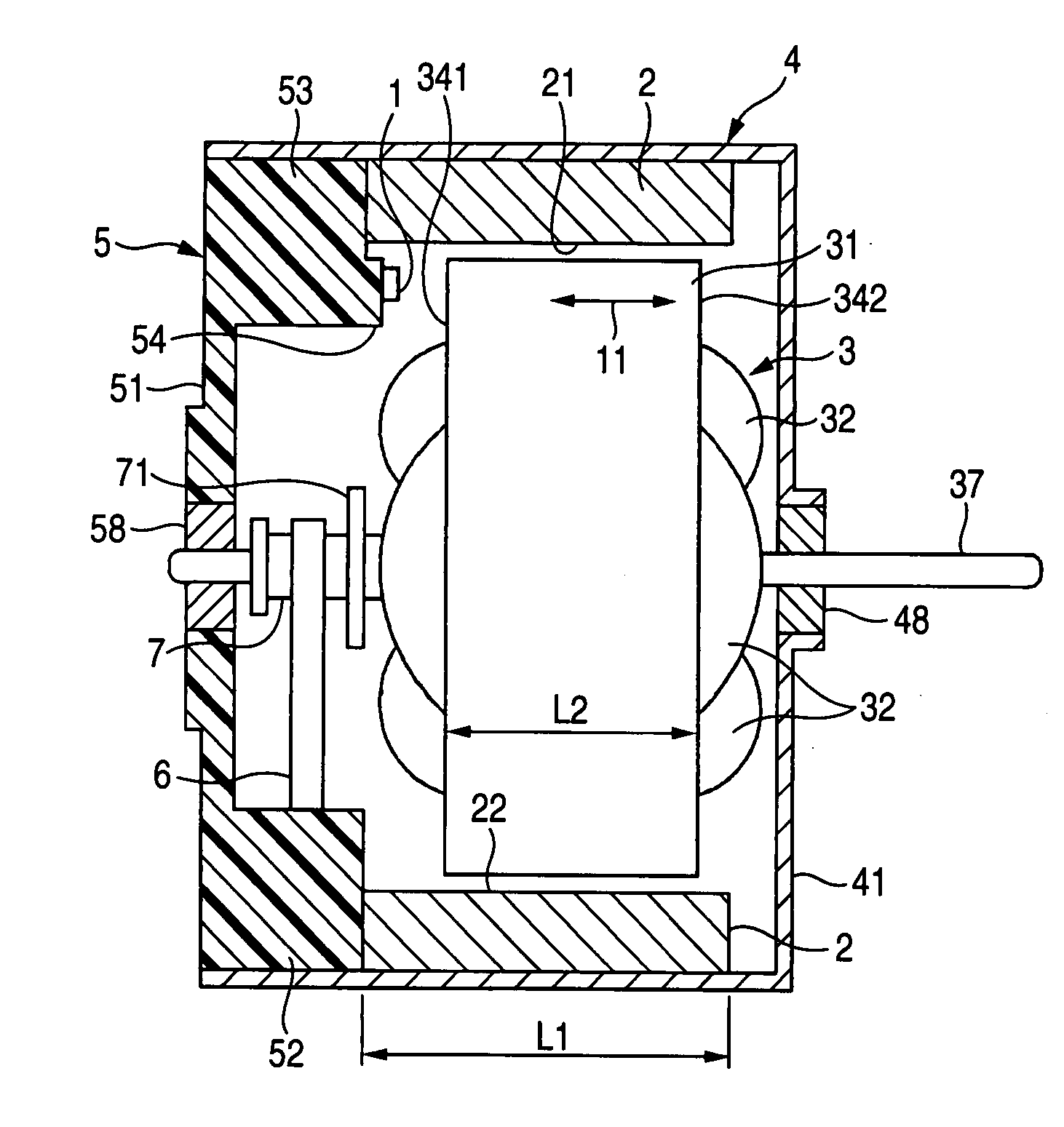
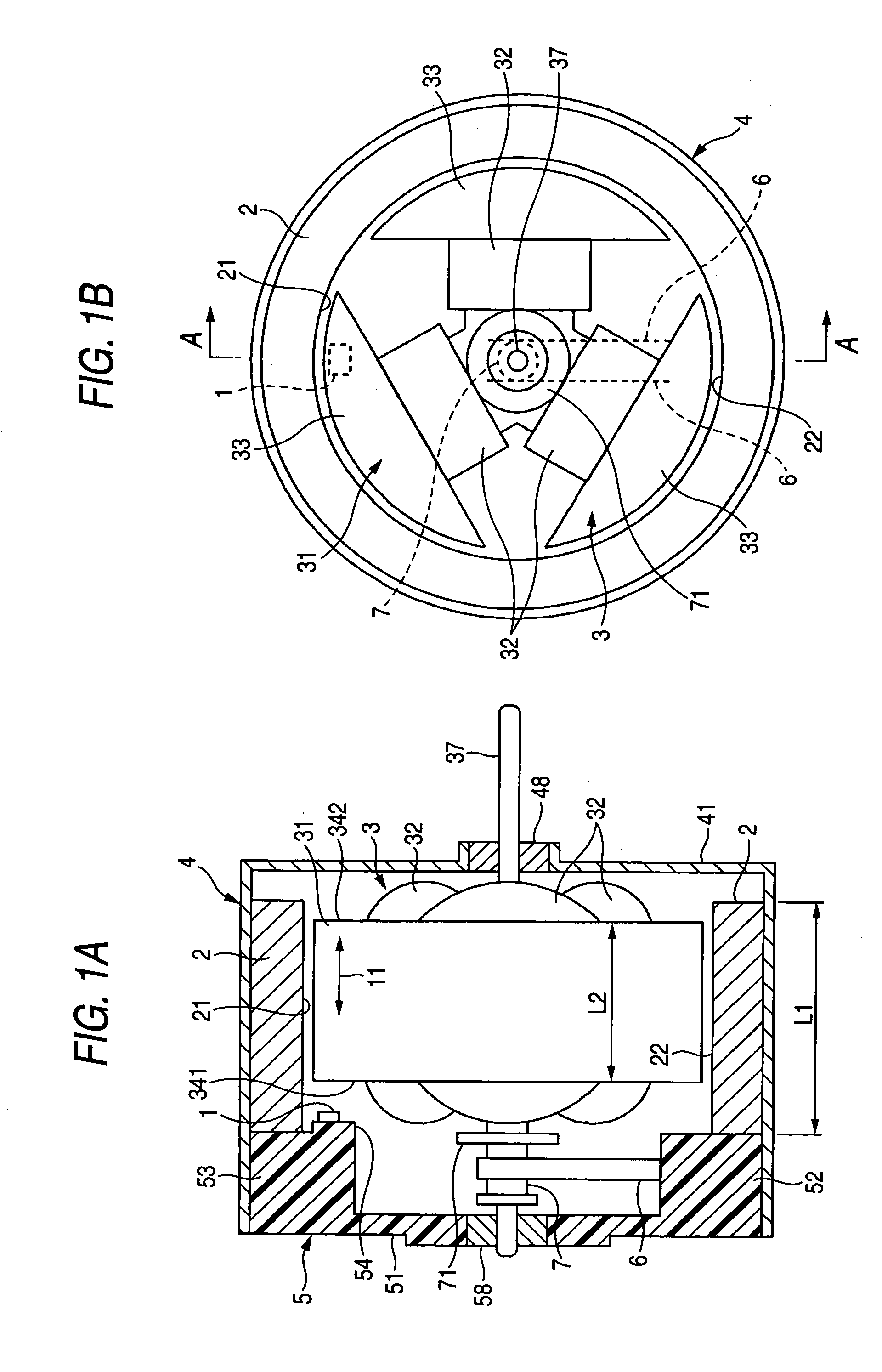
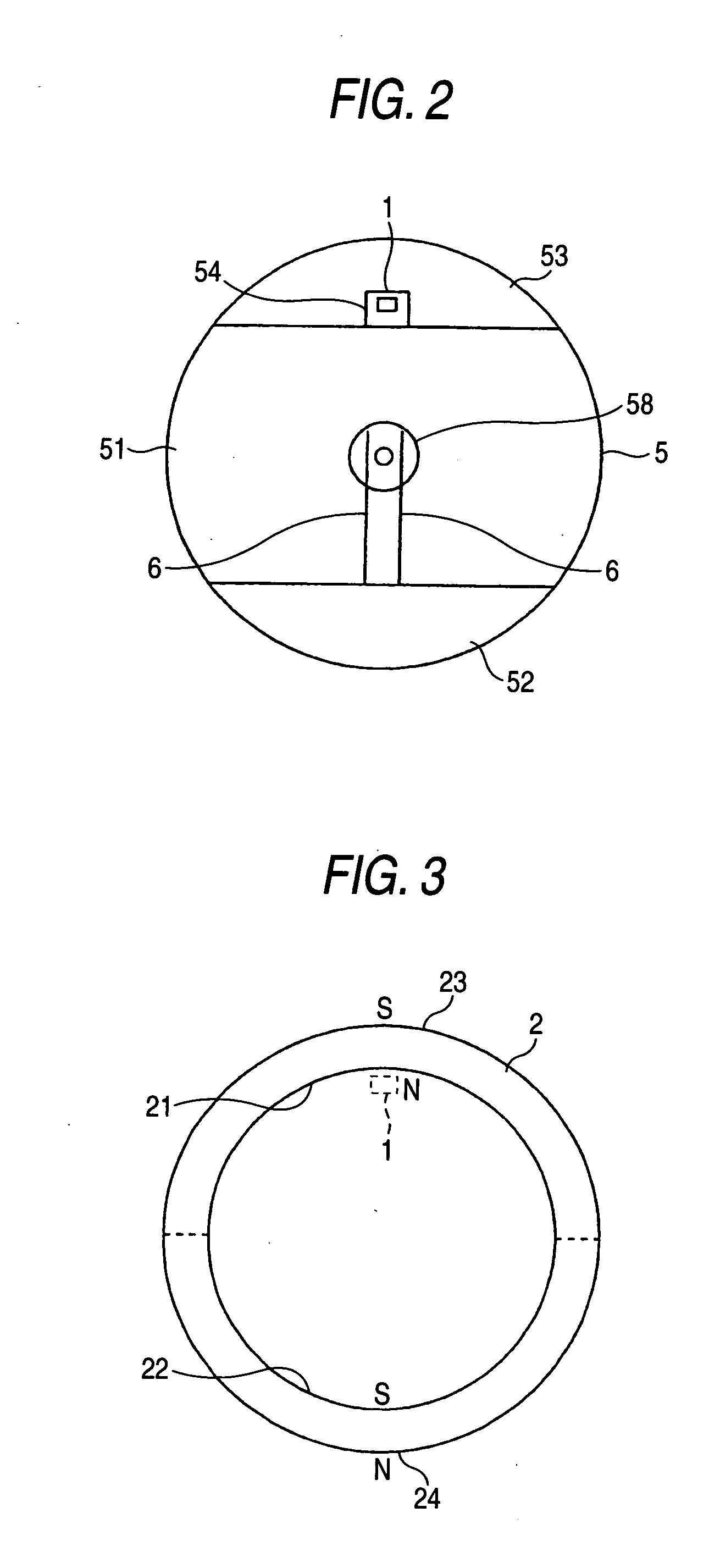
[0039] FIGS. 1A and 1B are structural diagrams illustrating the brush motor in accordance with the invention. FIG. 1B shows the shape as viewed from the rear side of the brush motor, and FIG. 1A shows a cross section taken along line A-A in FIG. 1B. In addition, FIG. 2 is a diagram of the shape of an end bell plate as viewed from the inner side.

[0040] In the drawings, an annular permanent magnet 2 for forming a field magnet is fitted to the inner periphery of a substantially cylindrical motor housing 4 whose one end portion is closed. A rotor 3 is rotatably supported by a bearing 58 provided in an end bell plate 5 and a bearing 48 provided in a disk-shaped front plate 41 of the motor housing 4. This rotor 3 has a rotor core 31 secured to a motor shaft 37, and the rotor core 31 has three arm portions 33. A rotor winding 32 is wound around each of the arm portions 33. Further, a commutator 7 is fitted on the motor shaft 37 on the end bell plate 5 side (reference numeral 71 denotes a n...

second embodiment

[0050] A description will be given of the operation of the second embodiment configured as described above.

[0051] It is now assumed that the rotor 3 is rotating clockwise as viewed in FIGS. 8A to 8C. In a case where the rotational position of the rotor 3 is that shown in FIG. 8A, i.e., in a case where the arcuate portion 34a which passed a position located in the vicinity of the Hall element 1a is located closer to the Hall element 1a than the arcuate portion 34b, the magnetic field formed between the inner peripheral surface 21 of the jutting-out portion of the permanent magnet 2 and the arcuate portion 34a passes through the Hall element 1a (indicated at 261). Further, when the rotor 3 has rotated from the rotational position shown in FIG. 8A through a slight angle, the magnetic field formed between the inner peripheral surface 21 of the jutting-out portion of the permanent magnet 2 and the arcuate portion 34b passes through the Hall element 1a (indicated at 262), as shown in FIG....

third embodiment

[0056] In addition, in the third embodiment, a waveform shaping circuit is used for generating accurate FG pulses with a simple circuit configuration without making the circuit configuration complex in both the forward rotation and reverse rotation of the rotor 3 on the basis of the output waveform produced due to the characteristics of the detection coil 1b. Referring to FIG. 11, a description will be given of a rotation control unit having this waveform shaping circuit.

[0057] A resistor R1 and a resistor R2 make up a voltage dividing circuit for dividing the voltage (5 V) of a plus power supply P in half. The voltage-divided output of 2.5 V is led as a reference voltage to a plus input of an OP amplifier 771 and a minus input of an OP amplifier 772. In addition, one terminal of the detection coil 1b is led to a minus input of the OP amplifier 771 through a resistor R3. The other terminal of the detection coil 1b is connected to the plus input of the OP amplifier 771. Further, a re...


PUM


Abstract

A brush motor has a magnetic sensor provided for detecting a change in a field magnet occurring in correspondence with a change in a rotational position of a rotor core.

Description

[0001] The present disclosure relates to the subject matter contained in Japanese Patent Application No. 2002-114316 filed Apr. 17, 2002, which is incorporated herein by reference in its entirety.[0002] 1. Field of the Invention[0003] The present invention relates to a brush motor provided with a magnetic sensor for detecting a change in a field magnet that occurs in correspondence with a change in a rotational position of a rotor core.[0004] 2. Description of the Related Art[0005] A frequency generator (hereafter referred to as FG) is used in the detection of the rotational speed of a dc motor. In the case of a brushless motor, a configuration has been proposed in which a sensor such as an FG coil for detecting the magnetic field from a rotating permanent magnet is provided (JP-UM-B-4-48145). In a brush motor, however, since the permanent magnet does not rotate, a conventional technique disclosed in JP-UM-B-7-13420 has been proposed.[0006] Namely, in this technique, a disk-like rot...

Claims


Application Information

Patent Timeline
IPC IPC(8): H02K11/00H02K23/66
CPCH02K23/66H02K11/0021H02K11/215
Inventor HIGUCHI, YOSHIO
Owner FUNAI ELECTRIC CO LTD
Why Eureka
Try Eureka