
Ink jet printer and image recording method

a technology of ink jet printer and image recording, which is applied in the direction of printing, other printing apparatus, etc., can solve the problems of non-uniform image, difficult for particle and dust to go inside the ink jet printer, and degradation of printed image quality

Inactive Publication Date: 2004-07-22
KONICA MINOLTA INC
View PDF13 Cites 72 Cited by
  • Summary
  • Abstract
  • Description
  • Claims
  • Application Information

AI Technical Summary

Benefits of technology

[0016] According to the first aspect of the present invention, operations of the drying member are controlled based on the temperature sensed by the temperature sensing section and on the humidity sensed by the humidity sensing section, so that it is made possible to add a photographic gloss to the surface of the recording medium by drying and thus removing an excessive solvent contained in the ink in the image formed on the recording medium, and carrying out the fixation of the image, based on the sensed temperature and sensed humidity inside the case. This is successful in further improving the glossiness of the image.
[0095] According to the sixth aspect of the invention, a combination of a plurality of inks used for forming the image by the image forming section is decided in consideration with the detected temperature and the detected humidity in the ink jet printer so that volume of the inks ejected to a predetermined unit area of the recording medium when the image is formed by the image forming section is not less than a predetermined value. After the image is formed at the decided combination of the plurality of inks, the image is fixed. This is successful in adding a photographic gloss to the surface of the recording medium and in further improving the glossiness of the image recorded on the recording medium.

Problems solved by technology

The pigment ink is superior to the dye ink in image storability, but inferior thereto in glossiness of the printed image while being adversely affected by scattered light or reflected light because the colorant molecule exists in a form of particle.
It has thus been anticipated that the printer disclosed in Patent Document 1 could not fully improve the glossiness of the printed image even after the fixation on the recording medium, and would result in only a degraded quality of the printed image.
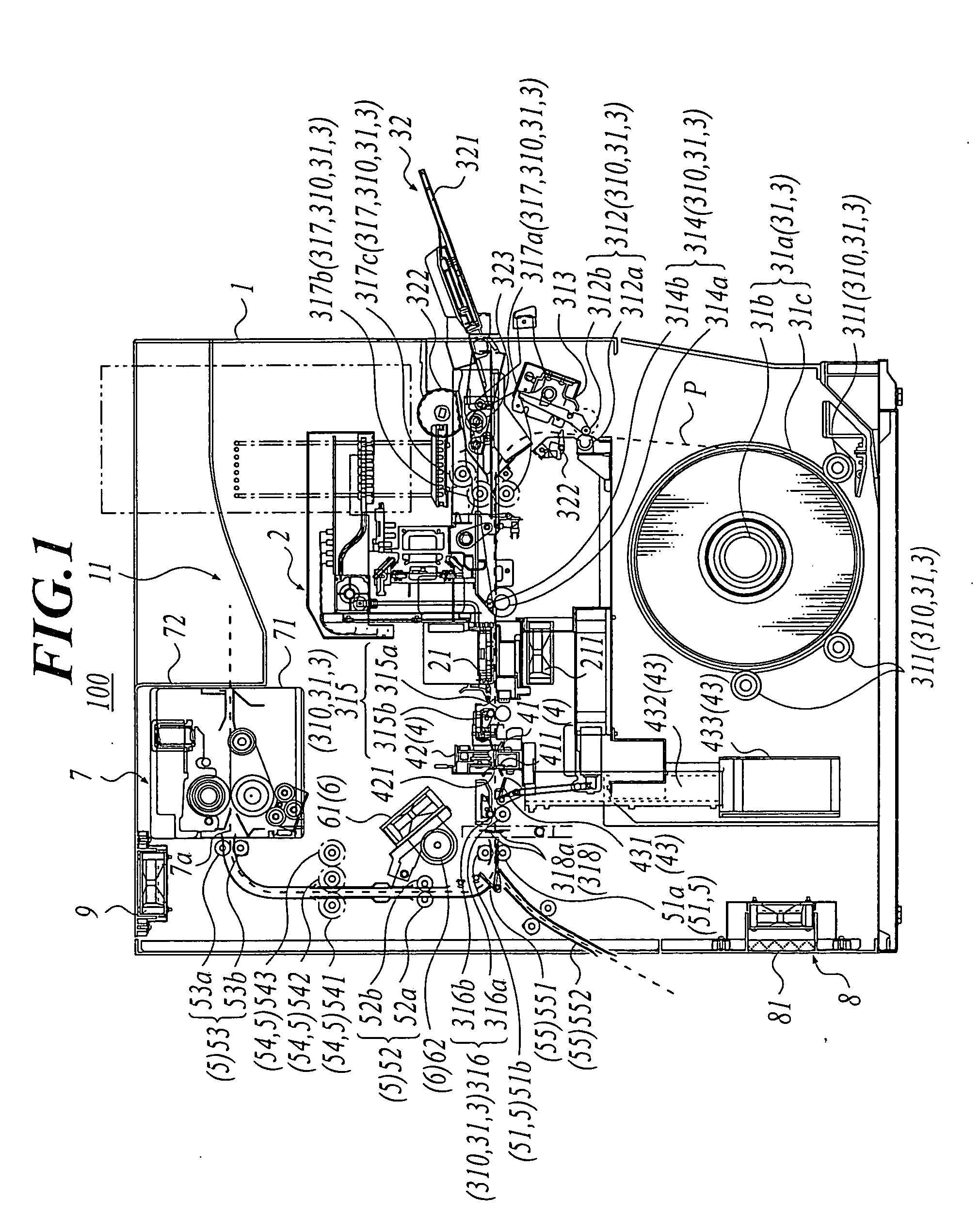
The air capacity of the intake fan 8 is set larger than that of the exhaust fan 9, and this makes it difficult for the particle and dust to go inside the ink jet printer 100.
More specifically, if the image formation is interrupted halfway and restarted later, the resultant image tends to be non-uniform due to misalignment of positions of the recording medium P or the ink ejection, before and after the interruption.

Method used


Image

  • Ink jet printer and image recording method
  • Ink jet printer and image recording method
  • Ink jet printer and image recording method

Examples


modified example 1

of Fixing Member

[0345] Modified example 1 of the fixing member will be explained referring to FIG. 11.

[0346] FIG. 11 is a transverse sectional view of a modified example of the fixing member.

[0347] A fixing member 700 in modified example 1 comprises a drive roller 727 which is disposed on the downstream side of the pressure roller 722 on the route of conveyance, and can rotate as being connected to a driving force source (not shown); and the pressure unit 72 which has a conveying belt 728 stretched between the drive roller 727 and the pressure roller 722.

[0348] The conveying belt 728 is disposed so as to align the surface thereof almost in parallel with the back surface of the recording medium P to be conveyed.

[0349] The conveying belt 728 has properties almost similar to those of the fixing belt 71d, and has constituents again almost similar to those of the fixing belt 71d.

[0350] The drive roller 727 is disposed so as to nearly oppose to the drive roller 71c of the heating unit 71....

modified example 2

of Fixing Member

[0352] Modified example 2 of the fixing member will be explained referring to FIG. 12.

[0353] FIG. 12 is a transverse sectional view of a modified example 2 of a fixing member 800.

[0354] The fixing member 800 of the modified example 2 has the heating unit 71 having the heating roller 71b which is disposed so as to oppose with the pressure roller 722, and can rotate under contact with the pressure roller 722.

[0355] The heating roller 71b is connected to a driving force source such as a drive motor (not shown), the pressure roller 722 can rotate while being driven by the rotation of the heating roller 71b, and the recording medium P can be conveyed based on cooperation of these rollers.

[0356] It is necessary for the heating roller 71b to have releasing property and durability, and also to have a smooth surface. Materials for composing the heating roller 71b which can satisfy the above-described needs will be explained.

[0357] Possible combinations of base / outer layer of ...

second embodiment

[0370]

[0371] The following paragraphs will describe an ink jet printer according to the second embodiment applied with the present invention, referring to FIGS. 16A and 16B.

[0372] It is to be noted that the second embodiment will have portions in common with the previous embodiment except for portions specific to the second embodiment, so that the common portions will be given with the same reference numerals as in the previous embodiment, and will not repeatedly be explained.

[0373] FIG. 16A is a block diagram showing a configuration of a main part of the control device 400 according to the second embodiment, and FIG. 16B is a view showing an internal structure of the ROM provided in the control device shown in FIG. 16A.

[0374] The ink jet printer of the second embodiment is configured as having no drying member and no drying control section, and as shown in FIG. 16A, in the combination deciding step during the image formation, a CPU 422a of a control section 420 reads, as a combinat...


PUM


Abstract

An ink jet printer includes: an image forming section for forming an image by ejecting a pigment ink toward a recording medium in which a surficial layer includes thermoplastic fine particles, in a case; a fixing member for fixing the image by heating and pressurizing the recording medium on which the image is formed by the image forming section; a drying member for drying the ink used for forming the image before the image is fixed to the recording medium by the fixing member; a temperature detecting member for detecting a temperature in the case; a humidity detecting member for detecting a humidity in the case; and a drying member control section for controlling an operation of the drying member in accordance with the temperature detected by the temperature detecting member and the humidity detected by the humidity detecting member.

Description

[0001] 1. Field of the Invention[0002] The present invention relates to an ink jet printer and an image recording method.[0003] 2. Description of the Related Art[0004] In recent years, images taken typically with digital cameras or the like, or stored in a data form in storage media such as flash memory and CD, are printed using ink jet printers which form images by ejecting inks onto recording media, rather than printed onto photographic paper.[0005] Both of dye ink and pigment ink are available for the image printing using the ink jet printer. The pigment ink is superior to the dye ink in image storability, but inferior thereto in glossiness of the printed image while being adversely affected by scattered light or reflected light because the colorant molecule exists in a form of particle. In the image printing using the ink jet printer and pigment ink, it has therefore been a general practice to use a pigment ink containing a dispersant, to form the image on a recording medium hav...

Claims


Application Information

Patent Timeline
Patent Type & Authority Applications(United States)
IPC IPC(8): B41J2/205B41J11/00
CPCB41J2/2056B41J11/002B41J11/0015B41J11/0022B41J11/0024
Inventor TSUTSUMI, TAKASHIOHYA, HIDENOBUSUZUKI, SHINICHIFUKUDA, TERUYUKIYASUDA, MINORU
Owner KONICA MINOLTA INC
Learn More