Compressed air treatment device that is designed to be installed in an industrial vehicle

a technology for industrial vehicles and treatment devices, applied in the direction of positive displacement liquid engines, braking systems, transportation items, etc., can solve the problems of installation and maintenance problems, numerous risks of leakage and improper contact, and existing architectures that have the disadvantage of localized installation of various components

Inactive Publication Date: 2004-07-22
RENAULT TRUCKS
View PDF6 Cites 26 Cited by
  • Summary
  • Abstract
  • Description
  • Claims
  • Application Information

AI Technical Summary

Problems solved by technology

It will be appreciated that the existing architectures have the disadvantage of a localized installation of the various components used for each of the functions described hereinabove.
The dispersion of these various components and the pro

Method used


Image

  • Compressed air treatment device that is designed to be installed in an industrial vehicle
  • Compressed air treatment device that is designed to be installed in an industrial vehicle
  • Compressed air treatment device that is designed to be installed in an industrial vehicle

Examples


Embodiment Construction

[0052] As already mentioned, the invention relates to an air treatment device intended to equip industrial vehicles such as trucks in particular.

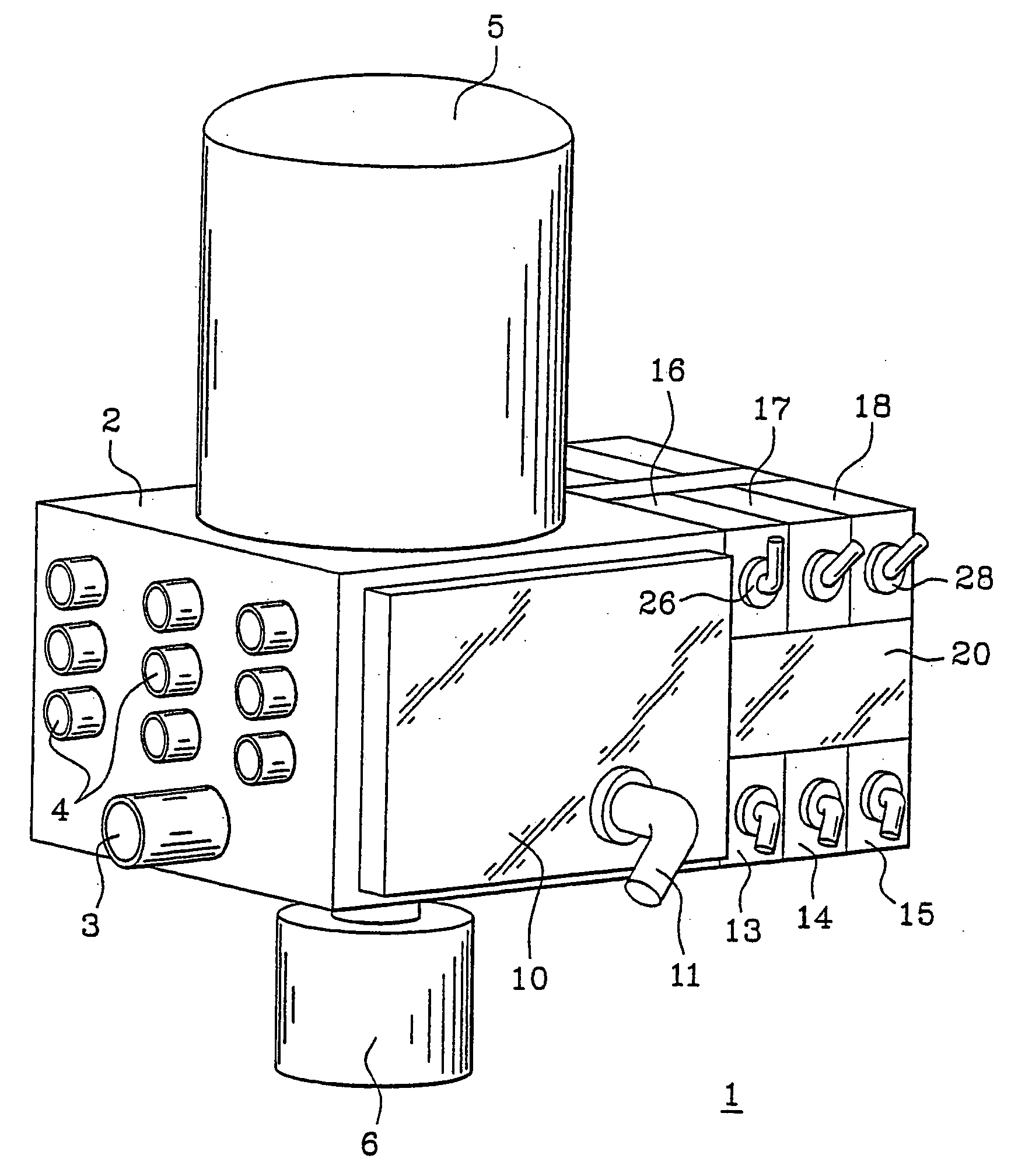
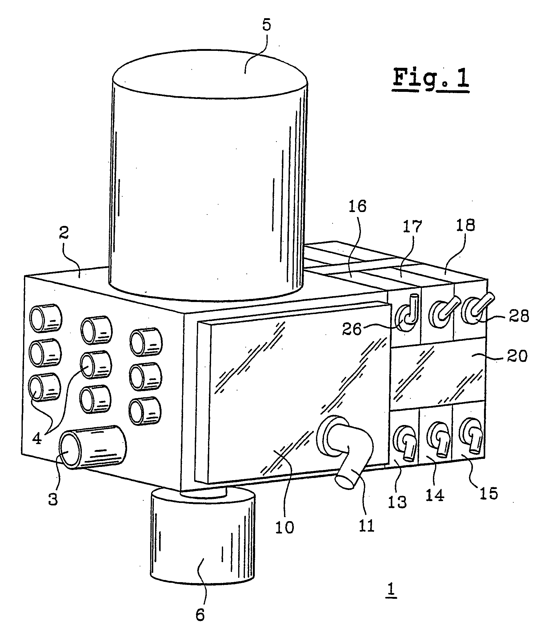
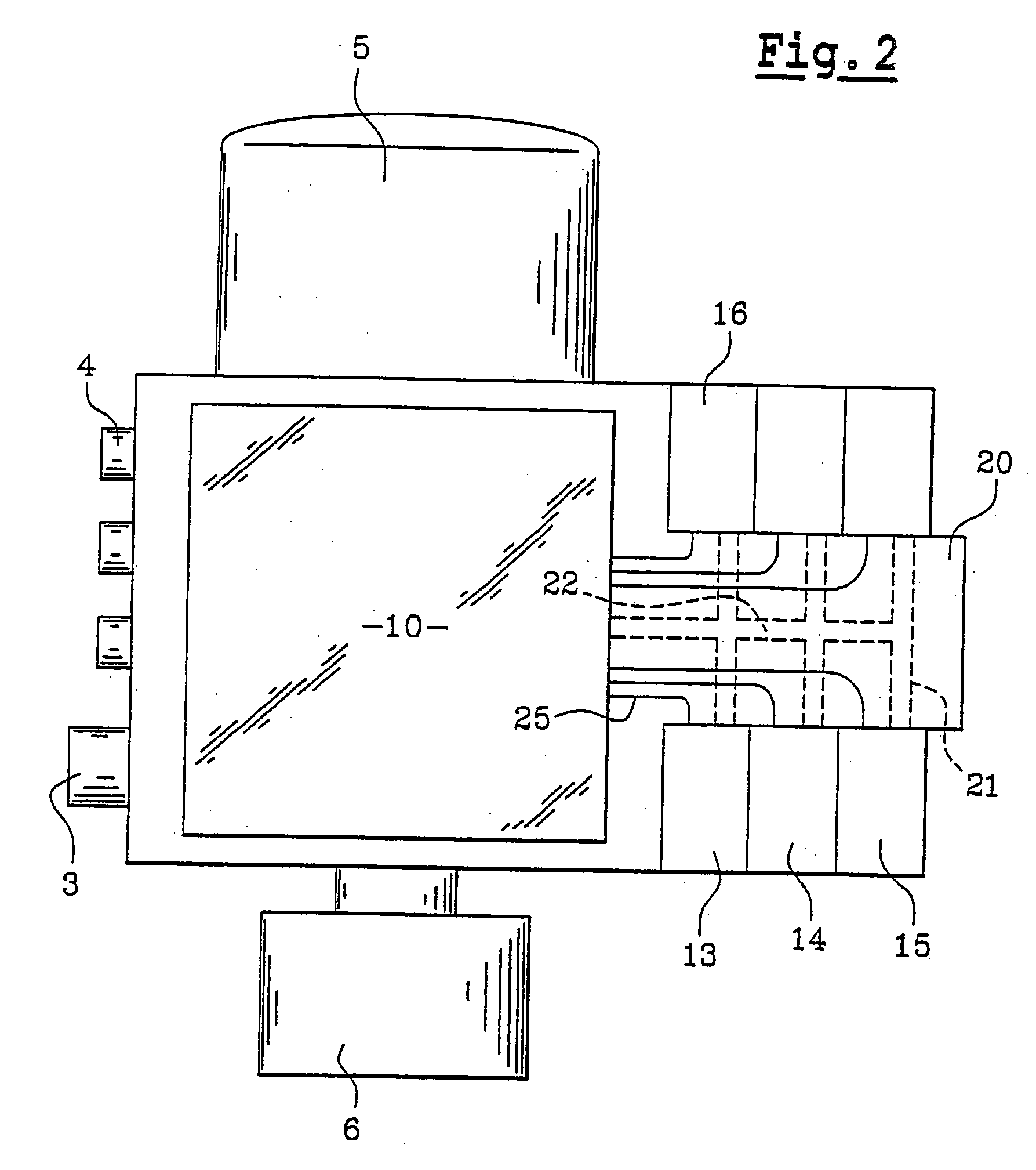
[0053] In one particular embodiment, this device is in the form illustrated in FIG. 1. Thus, in general, the air treatment device (1) comprises a main body (2) equipped with an air inlet (3) which is intended to be connected to the compressor, itself driven by the engine.

[0054] The body (2) also comprises a plurality of air outlets (4) intended in particular to supply the front and rear service braking circuits of the motor vehicle, and certain other devices operating on compressed air such as the clutch assistance systems for example, on automatic transmissions.

[0055] The number of air outlets (4) illustrated in FIG. 1 is given by way of example, it being understood that the invention covers alternative forms in which the number of outlets is lower or higher than the number illustrated.

[0056] The body (2) also accommodates an air dehumidif...


PUM


Abstract

A compressed air treatment device is designed to be installed in an industrial vehicle consisting of a motor vehicle that can pull a trailer. The device comprises: an inlet for air from a compressed air source; at least one air outlet which is connected to a tank that is intended to supply the service braking system; a set of electropneumatic components for distributing the compressed air which comes from the compressed air source and which is intended for the tank(s); an electronic control unit which can control said set of electropneumatic components, the control unit being connected to a computer communication bus and to various electrical components such as sensors or switches. The device also comprises: a supplementary air outlet which is intended to supply the control element(s) for the pneumatic suspension system of an axle; a supplementary set of electropneumatic components which are associated with the supplementary air outlet; control means which are integrated in the electronic control unit to control the supplementary set of electropneumatic components according to information originating from the computer communication bus and/or various electrical components.

Description

[0001] The invention relates to the technical field of electropneumatic components particularly those used in industrial vehicles such as trucks or the like. It relates more specifically to a compressed-air treatment device which combines both the supply of the main braking system or service brake, with the supply of the various other systems that employ compressed air as a source of power.PRIOR ART[0002] In general, industrial vehicles, particularly trucks, are equipped with a braking system that operates on compressed air. This compressed air is produced by a pneumatic compressor driven by the engine. This compressor delivers compressed air which is stored in an air reservoir intended to supply the service brake circuit. In that way, when the driver operates the brake pedal, the compressed air contained in the reservoir concerned supplies the pneumatic circuit thus braking the motor vehicle.[0003] The same arrangement is used for the service braking of the trailer, when the latter...

Claims


Application Information

Patent Timeline
IPC IPC(8): B60G17/052B60T8/32B60T17/18
CPCB60G17/0523B60G2206/0116B60T17/18B60T8/3285B60G2500/203Y10T137/6914
Inventor DUCHET, BRUNOCARNEIRO ESTEVES, ARMANDO
Owner RENAULT TRUCKS
Why Eureka
Try Eureka