Resin transfer molding process

a technology of resin transfer molding and resin injection, which is applied in the direction of transportation and packaging, manufacturing tools, and other domestic objects, can solve the problems of low initial capital investment cost of resin transfer molding, and inability to properly design the tool to tak

Inactive Publication Date: 2004-08-05
THE BOEING CO
View PDF24 Cites 35 Cited by
  • Summary
  • Abstract
  • Description
  • Claims
  • Application Information

AI Technical Summary

Benefits of technology

0039] The present invention further provides a method of forming a radius filler for use in forming a preform to be used in a resin transfer molding process, the method including providing unidirectional tows, and braiding a sleeve of fibers around the unidi

Problems solved by technology

These subassemblies usually require labor-intensive shimming, bonding, mechanical fastening, and sealing.
The initial capital investment costs of resin transfer molding are low when compared with many other molding processes.
One of the problems encountered when using resin transfer molding is that complex cavities that extend into the surface of the part must be formed in the mold cavity surface, or the complex cavity will be filled by resin during the resin injection process.
If the part includes an internal hollow tube, proper design of the tool to take this into account may be difficult and expensive, or may produce a tooling configuration from which removal of the finished part would be difficult.
Other problems are encountered in laying up or arranging preforms of fibers prior to placing the preform into the mold.
If braided or woven fabric is used, cutting of that fabric often results in frayed edges, which is undesirable.
Arranging stacks, or tapered-of

Method used


Image

  • Resin transfer molding process
  • Resin transfer molding process
  • Resin transfer molding process

Examples


Embodiment Construction

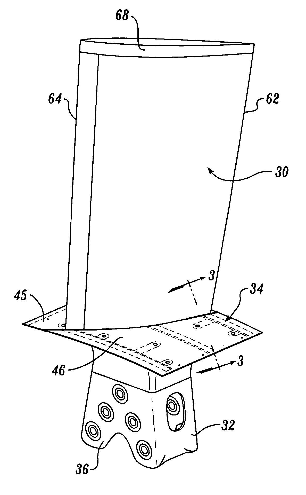
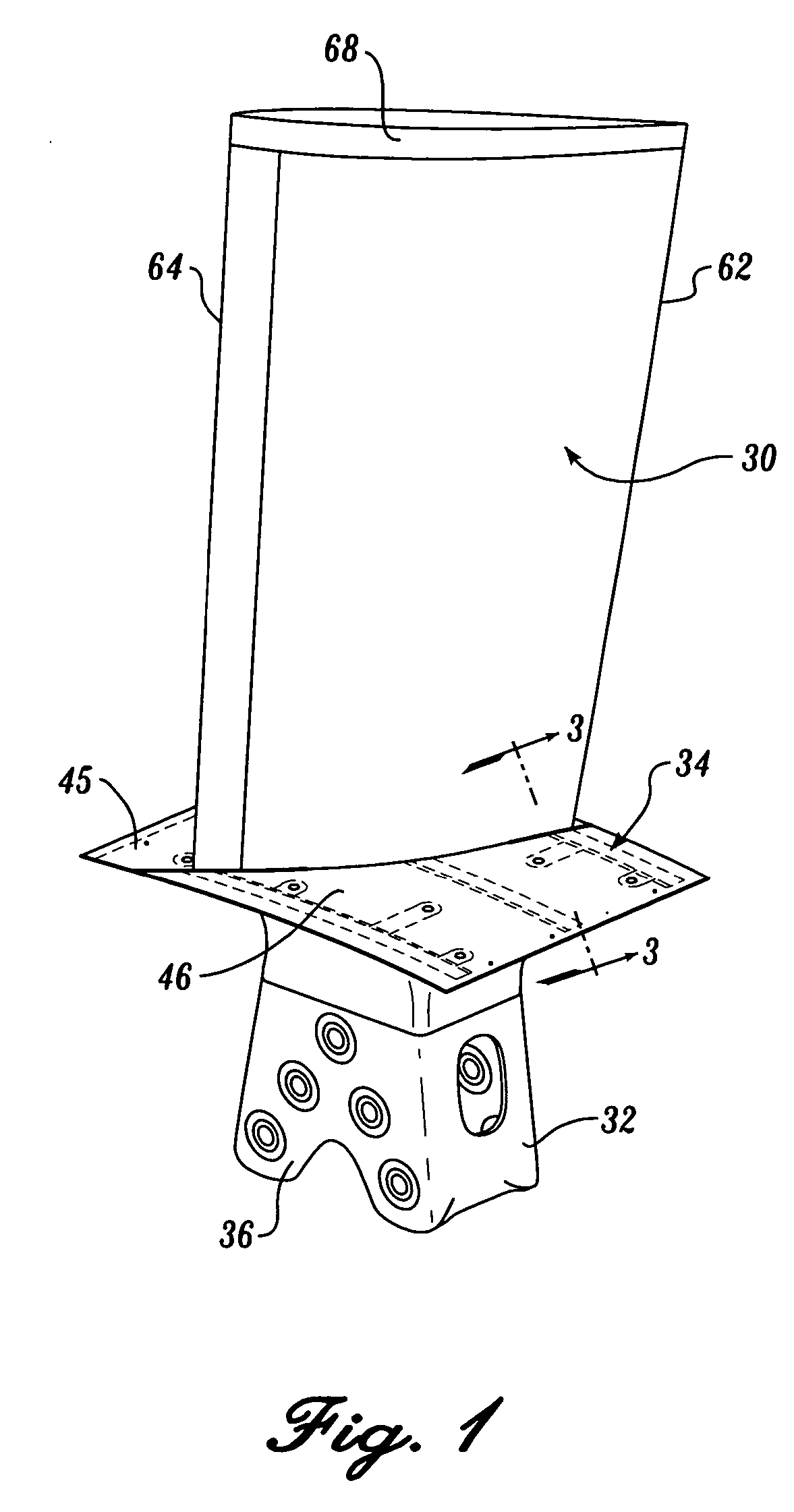
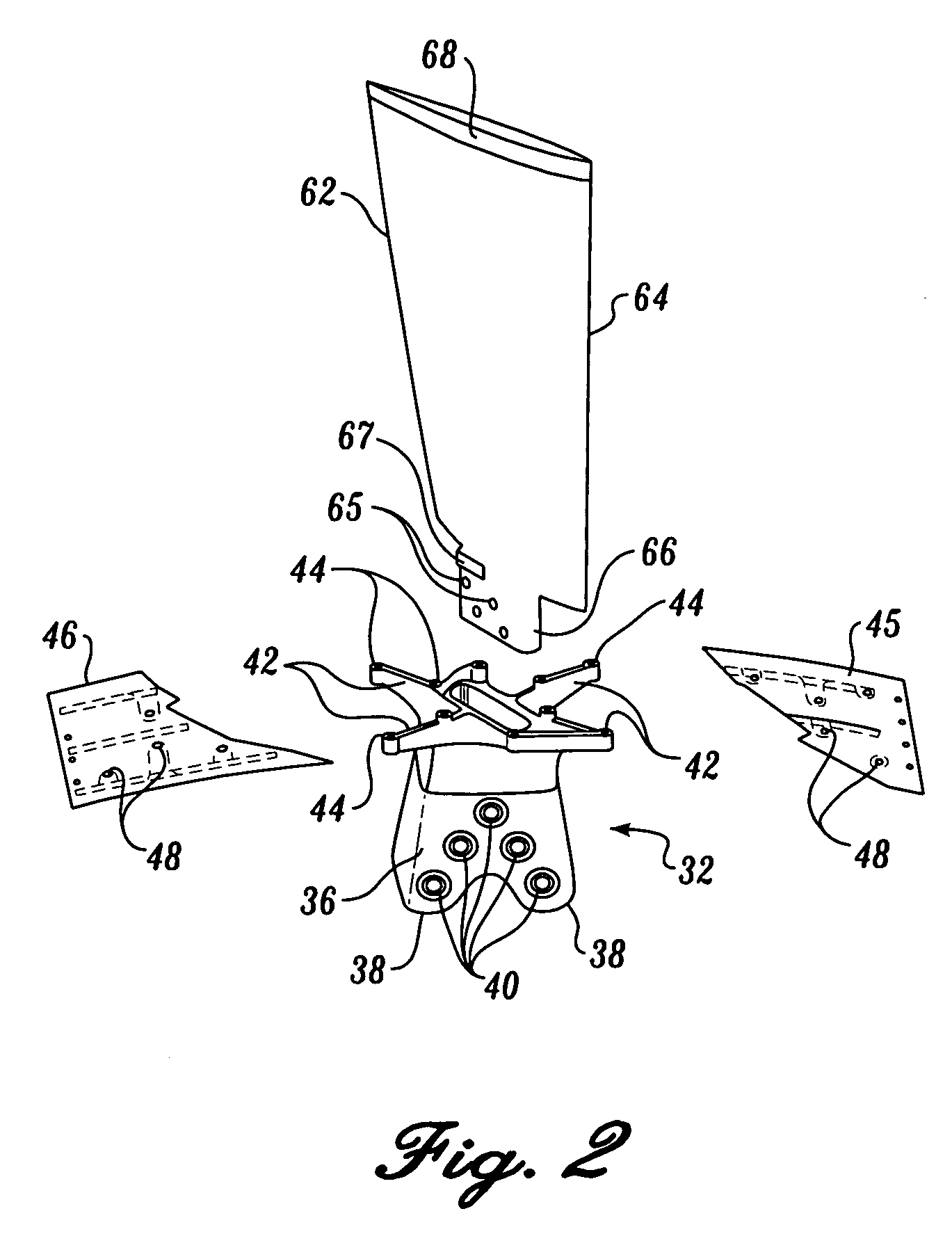
[0076] Referring now to the drawing, in which like reference numerals represent like parts throughout the several views, FIG. 1 shows a wind tunnel blade 30 made in accordance with the present invention. The wind tunnel blade 30 is connected to a base 32 and is held in position by a two-piece cuff 34.

[0077] Briefly described, the present invention is directed to the separate wind tunnel blade 30, base 32 and cuff 34 system, and the unique configuration and structure of the wind tunnel blade 30. In addition, the present invention is directed to resin molding transfer processes for forming the wind tunnel blade 30.

[0078] The base 32 is designed to be attached to a hub of a wind tunnel fan (not shown). A plurality of the wind tunnel blades 30 project radially outward from the hub and are supported therefrom in a conventional fashion at the base 32. Any number of wind tunnel blades 30 can be used with the wind tunnel fan. As a nonlimiting example, the wind tunnel blade 30 shown in FIG. ...


PUM


Abstract

A wind tunnel blade (30) connected to a base (32) and held in position by a two-piece cuff (34). The wind tunnel blade (30) is formed in a resin transfer molding process in which central, fore, and aft foam core sections (70, 72, 74) are placed together to form the wind tunnel blade (30). Radius fillers (120) are used to fill the gaps between the outer edge of the foam core sections. The radius fillers (120) used in the wind tunnel blade (30) are formed by a braided sleeve (122) surrounding a number of unidirectional tows (124). A tip (68) is formed separately from the rest of the wind tunnel blade (30) and is glued to the top thereof. Stacked layers of braided fibers (100) are used to reinforce the central core section (70).

Description

CROSS-REFERENCE TO RELATED APPLICATIONS[0001] This application is a divisional of application Ser. No. 10 / 448,527, filed May 30, 2003, which in turn is a divisional of application Ser. No. 09 / 826,478, filed on Apr. 4, 2001, now U.S. Pat. No. 6,589,618, which in turn is a divisional of U.S. application Ser. No. 09 / 115,568, filed Jul. 14, 1998, now U.S. Pat. No. 6,231,941, priority from the filing dates of which is hereby claimed under 35 U.S.C. .sctn. 120.FIELD OF THE INVENTION[0002] This invention relates to a process of resin transfer molding lightweight, foam-filled products and the strong, lightweight products made thereby. More particularly, the present invention is directed to a process of resin transfer molding a wind tunnel blade and the structure of the wind tunnel blade.BACKGROUND OF THE INVENTION[0003] Resin transfer molding has been around for many decades, and its use has grown considerably in recent years. The process allows the economical manufacture of high quality co...

Claims


Application Information

Patent Timeline
IPC IPC(8): B29C70/08B29C70/44B29D99/00
CPCB29C70/083B29C70/086B29C70/443B29D99/0025B29L2031/08Y10T428/249986Y10T428/24504Y10T428/1369Y10T428/24496Y10T403/7047Y10T428/24008Y10T428/1348Y10T428/2457B29D99/0005
Inventor CUNDIFF, THOMAS R.BENNETT, HENRY H.LUND, BRAD G.RENZ, ROBERT S.WRIGHT, DONALD E.
Owner THE BOEING CO
Why Eureka
Try Eureka