
Transducer for distance measurement

a technology of transducer and distance measurement, which is applied in the field of transducer for distance measurement, can solve the problems of casing also becoming worn, and achieve the effect of simple solution and increased measuring accuracy

Inactive Publication Date: 2004-09-02
DAPROKS AB
View PDF12 Cites 4 Cited by
  • Summary
  • Abstract
  • Description
  • Claims
  • Application Information

AI Technical Summary

Benefits of technology

[0004] The object of the invention is to produce an improved transducer offering increased measuring accuracy in connection with wear of the transducer head. Another object is to achieve this with a simple solution.
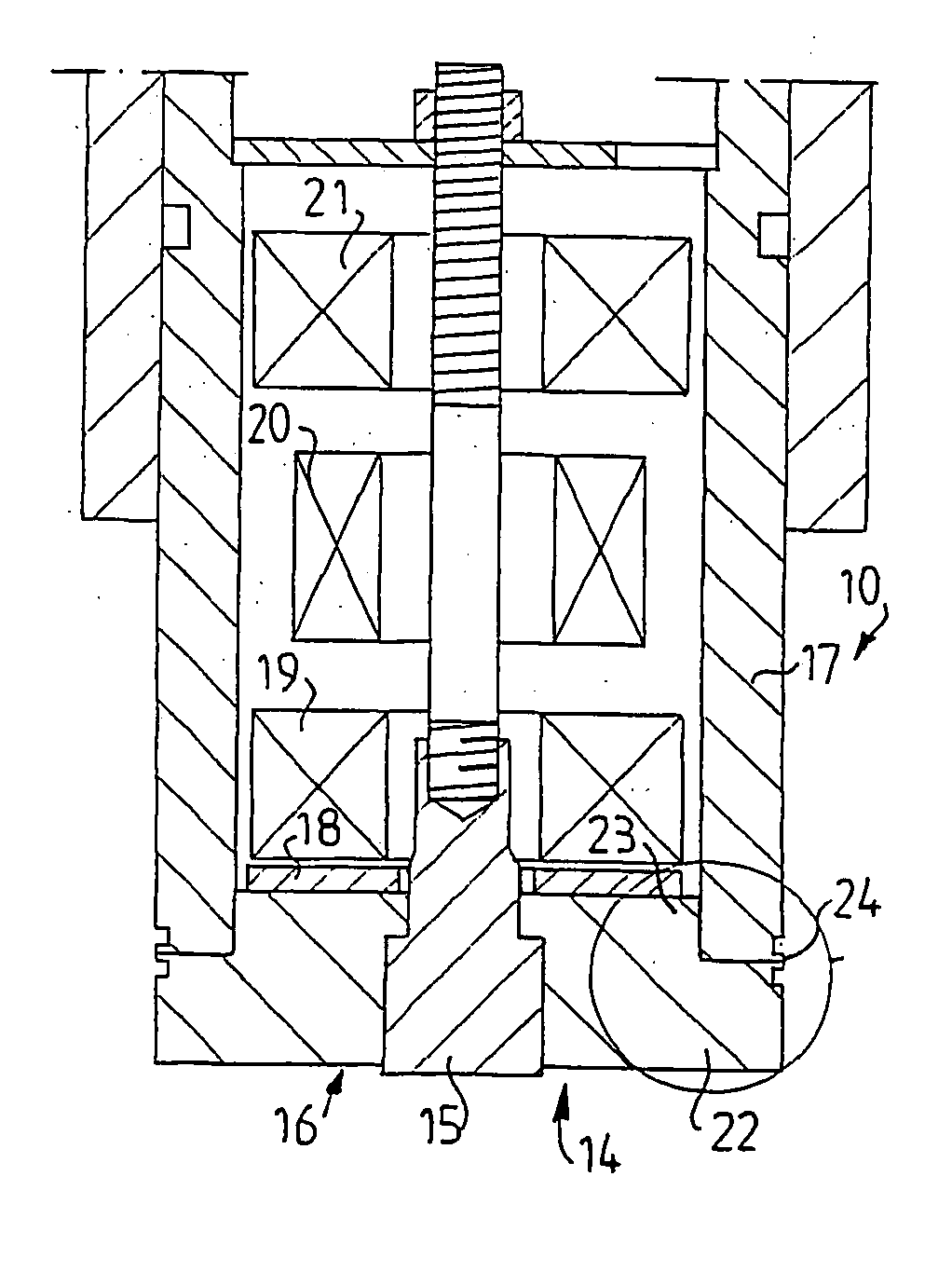
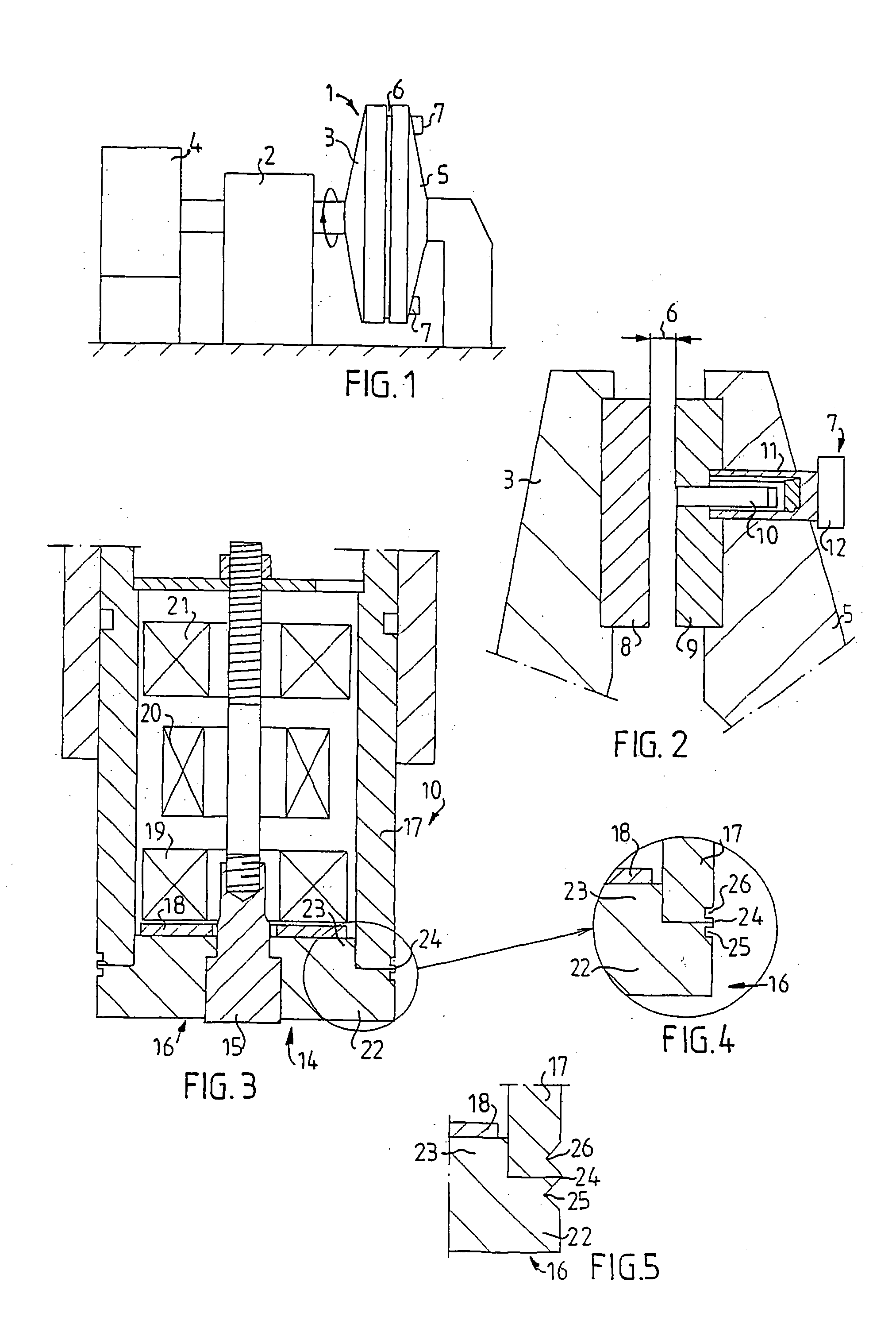
[0006] By realizing the holder in the transducer head in such a way that it reaches axially beyond the end of the casing, the effect is that only the holder and the actual measuring pole will become worn. Previously, when the holder was fully incorporated in the casing of the transducer, the casing also became worn.
[0007] The solution according to the invention has the effect that the measuring situation for the transducer is changed less than previously in the event of wear and tear, resulting in increased precision.
[0008] The solution according to the invention also makes it reliably easy to obtain very good sealing of the active end of the transducer by means of an external joint.

Problems solved by technology

Previously, when the holder was fully incorporated in the casing of the transducer, the casing also became worn.

Method used


Image

  • Transducer for distance measurement
  • Transducer for distance measurement
  • Transducer for distance measurement

Examples


Embodiment Construction

[0019] FIG. 1 shows in diagrammatic representation those parts of a refiner-type machine 1 intended for paper pulp production which are necessary to an understanding of the invention. This machine is provided with a rotor 3 mounted rotatably in a stand 2, which rotor is driven by a motor 4 and can also be axially shifted in the direction to and from a stator 5 so as to adjust the size of a beating gap 6 between the rotor 3 and the stator 5. In order to check the size of the beating gap 6, in the stator 5 there is mounted at least one transducer device 7, having a transducer which is of the magnetic type and which expediently works according to the reluctance principle. This type of transducer is well known to persons skilled in the art. Two or more transducer devices 7 can expediently be present, distributed around the stator 5.

[0020] As can be seen in greater detail from FIG. 2, both the rotor 3 and the stator 5 are provided with beating segments 8, 9, which have a surface suitable...


PUM

PropertyMeasurementUnit
Lengthaaaaaaaaaa
Diameteraaaaaaaaaa

Abstract

A transducer (10) for distance measurement, especially between a stator and a rotor in a refiner for paper pulp production, in which the transducer is of the magnetic type and has a tubular casing (17), the one end of which forms a measuring head (14), in which a measuring pole (15) is fitted in a holder (16) which is mounted in the end of the casing (17) and seals this. The holder (16), with a first portion (22) of its axial length, reaches beyond the end of the casing. This first portion (22) and the measuring pole (15) are intended to be able to be worn away to a smaller axial length during use of the transducer, whilst the length of the casing is maintained.

Description

[0001] The present invention relates to a transducer for distance measurement, especially between a stator and a rotor in a refiner for paper pulp production, according to the preamble to Patent Claim 1.PRIOR ART[0002] In refiners intended for paper pulp production, the size of the beating gap between a stator and a rotor changes during operation as a result of wear and tear on the mutually facing beating segments on the stator and rotor. For quality reasons, it is desirable to have good control over the size of the beating gap and to be able to compensate for wear and tear or change the size of the beating gap for other reasons. Refiners of this type usually have long operating periods, often several months, so that the size of the beating gap should be able to be monitored during operation.[0003] In order to be able to measure the size of the beating gap, it is known to use magnetic-type transducers which are placed in the stator, with the end surface of the measuring head on a le...

Claims


Application Information

Patent Timeline
IPC IPC(8): G01B7/00B02C7/14D21D1/00D21D1/30G01B7/14
CPCB02C7/14G01B7/14D21D1/30D21D1/002
Inventor AKERBLOM, BENGTLOFQVIST, BENGT
Owner DAPROKS AB
Learn More