
Heat exchanger unit

a heat exchanger and unit technology, applied in the field of heat exchanger units, can solve the problems of condensation water at the heat exchange element, dew condensation inside the unit, and inability to completely inhibit the freezing of the heat exchange elemen

Inactive Publication Date: 2004-09-16
DAIKIN IND LTD
View PDF3 Cites 20 Cited by
  • Summary
  • Abstract
  • Description
  • Claims
  • Application Information

AI Technical Summary

Problems solved by technology

Furthermore, if such a heat exchanger unit is used in an environment where the outside air temperature falls below -10.degree. C., condensed water may freeze at the heat exchange element.
In addition, dew condensation may form inside the unit.
In such an environment, it may not be possible to completely inhibit freezing of the heat exchange element just by executing a fixed intermittent operation control mode when the temperature falls below a predetermined level, as is done conventionally.
Consequently, even if there is an increased risk of the outside air temperature falling below the second level and the heat exchange element freezing, freezing of the heat exchange element will be inhibited because the time in which the heat exchange element is cooled by the outside air (the time that the supply air fan is operating) will shorten.
Furthermore, if the supply air is stopped and just the exhaust air flows, entry of the outside air of the outdoor space into the indoor space through a gap prevents the indoor temperature from rising; consequently, the enhanced effect of inhibiting freezing cannot be obtained as when both the supply air and exhaust air are stopped.
Nevertheless, because the conventional art is unable to judge based only on the outside air temperature whether the heat exchange element will freeze, it is therefore preferable to make such judgments based on the temperature of the portion of the heat exchange element on the downstream side of the exhaust air flow, i.e., the portion that tends to freeze easily.

Method used


Image

  • Heat exchanger unit
  • Heat exchanger unit
  • Heat exchanger unit

Examples


first embodiment

[0037] First Embodiment

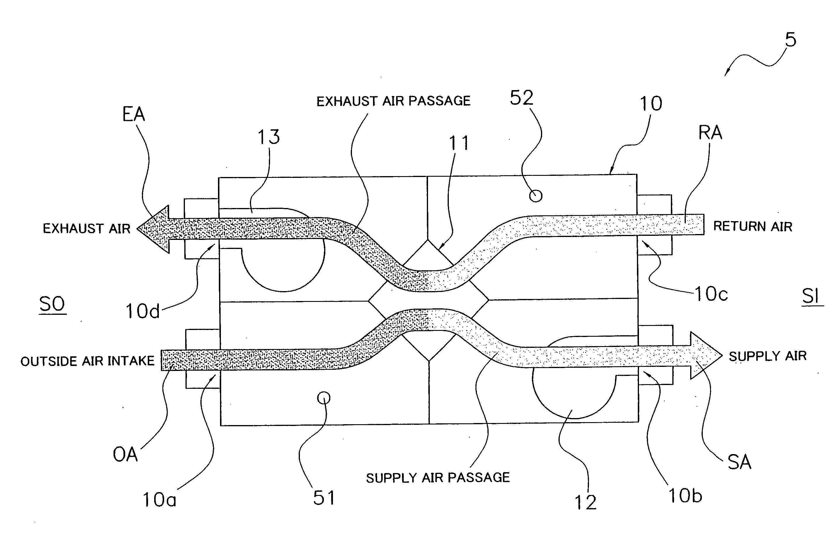
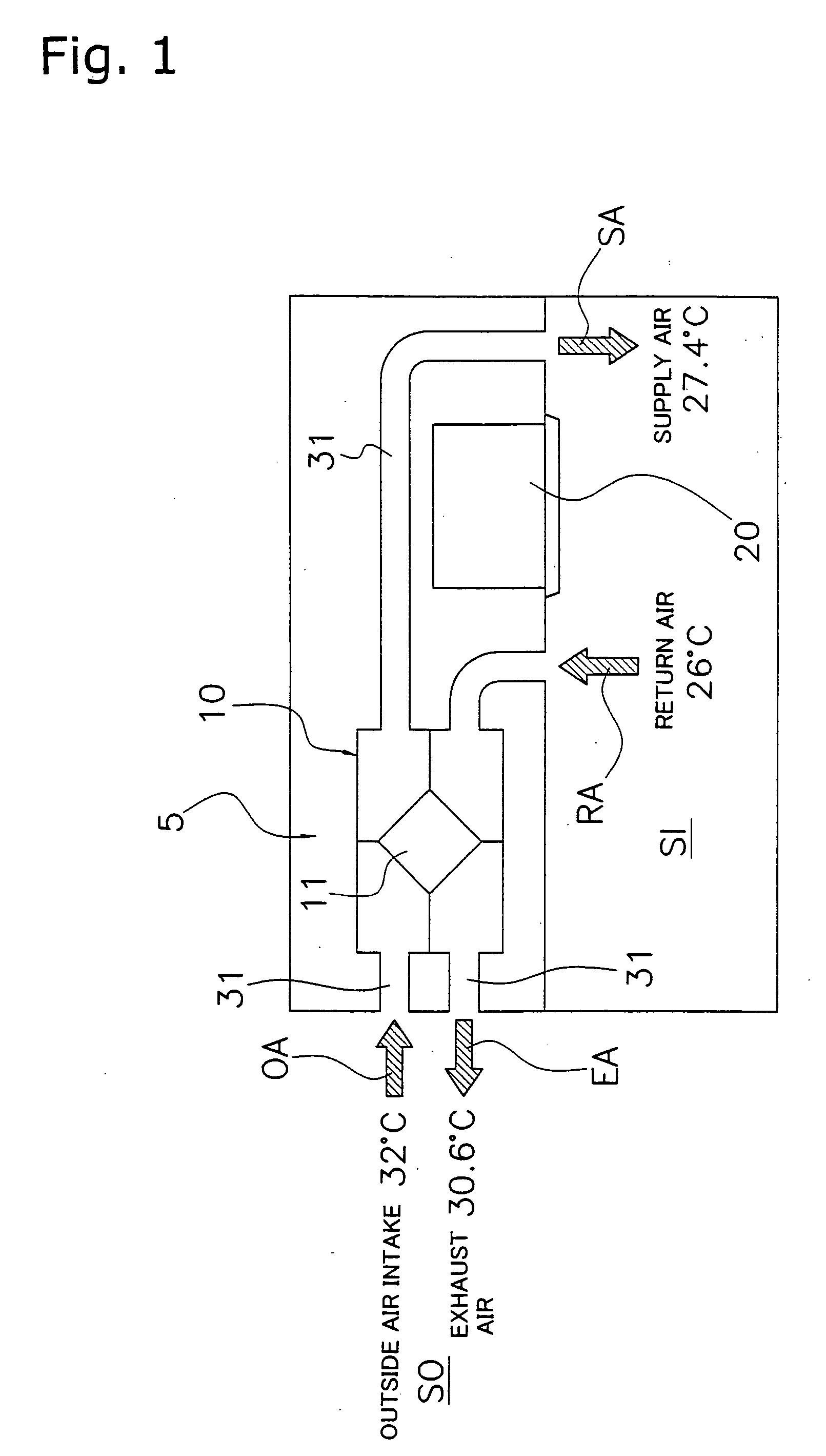
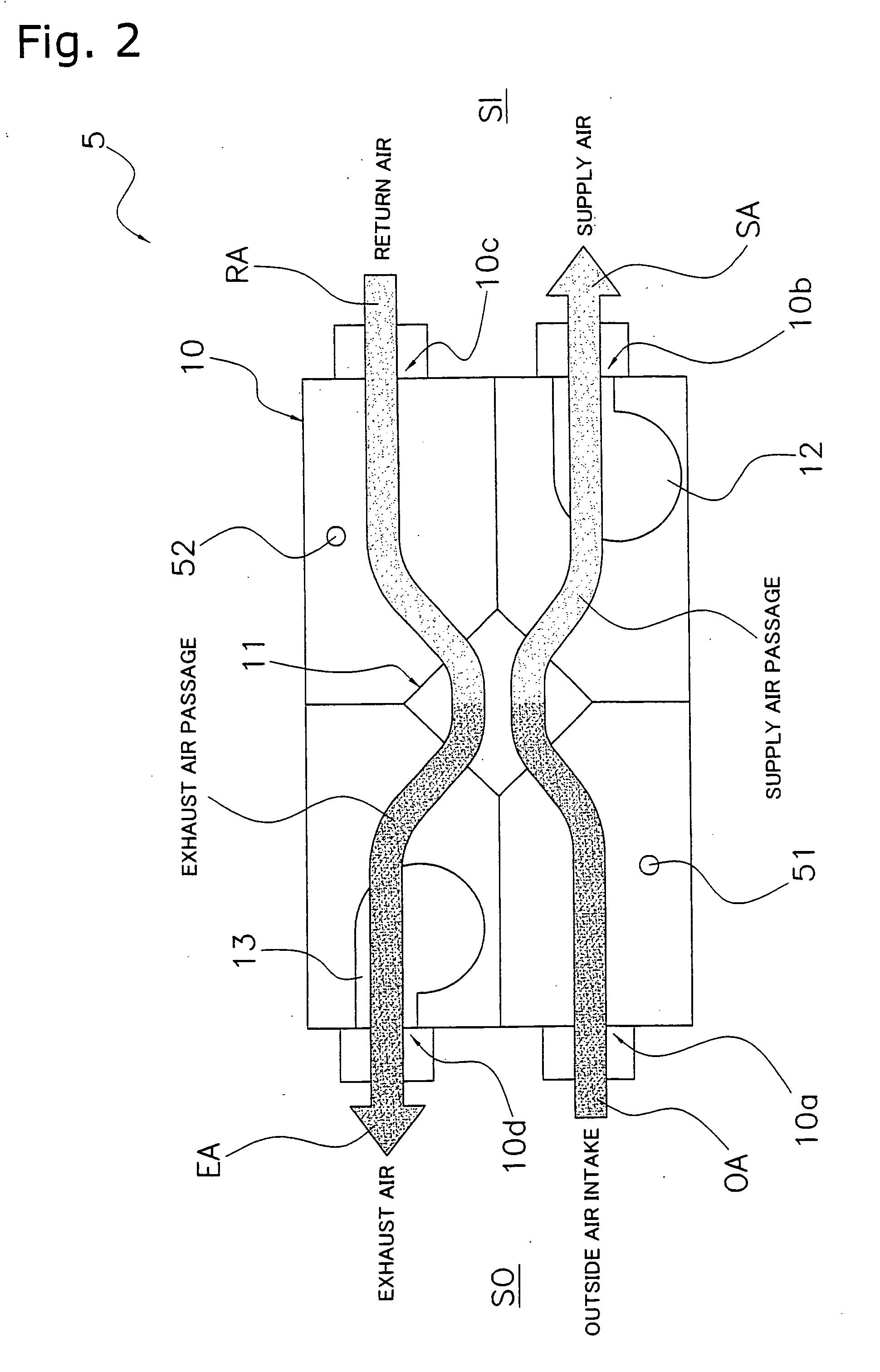
[0038] The heat exchanger unit 5 according to one embodiment of the present invention is linked to an air conditioner 20 or operates independently, and is installed in order to ventilate buildings and various facilities. As shown in FIG. 1, the heat exchanger unit 5 according to the present embodiment is installed in places like above the ceiling of an indoor space SI that is to be ventilated inside a building, and the duct 31 links the indoor space SI to the outdoor space SO outside the building. The heat exchanger unit 5 exchanges heat between the return air RA from the indoor space SI and the outside air OA by the heat exchange element 11, discharges the return air RA to the outdoor space SO (exhaust air EA), and then delivers post heat-exchanged outside air OA into the indoor space SI as supply air SA. In addition to this type of heat exchange and ventilation operation, the heat exchanger unit 5 can also perform the usual ordinary ventilation operation by ...

second embodiment

[0070] Second Embodiment

[0071] To provide a significantly different degree of inhibiting freezing of heat exchange element 11 between the first operational mode in the first freeze inhibit control mode and the second operational mode in the second freeze inhibit control mode in the above first embodiment, the first operational mode temporarily halts just the supply air fan 12, whereas the second operational mode temporarily halts both the supply air fan 12 and the exhaust air fan 13.

[0072] However, a case is also conceivable wherein, depending on the low-temperature resistance of the heat exchange element 11 and the ability of the air conditioner 20 to warm the indoor space SI, the abovementioned powerful second operational mode is not needed. In such a case, it is also possible to set the following type of first freeze inhibit control mode and second freeze inhibit control mode.

[0073] In the second embodiment, just the supply air fan 12 is temporarily stopped for a predetermined pe...

third embodiment

[0074] Third Embodiment

[0075] In the abovementioned first embodiment, the start and cancellation of the first freeze inhibit control mode and the second freeze inhibit control mode are judged based only on the temperature detected by the temperature sensor 51, which detects the outside air temperature; however, that judgment may also be made taking into consideration the conditions of the temperature detected by the temperature sensor 52, which detects the indoor temperature. In this case, the risk of freezing of the heat exchange element 11 can be more accurately estimated, making it possible to more appropriately time the start and cancellation of the first freeze inhibit control mode and the second freeze inhibit control mode.


PUM


Abstract

The present invention provides a heat exchanger unit (5) that can appropriately inhibit freezing of a heat exchange element (11), even in cold-climate regions. The heat exchanger unit (5) performs heat exchange and ventilation between an indoor space (SI) and an outdoor space (SO), and is therefore provided with a heat exchange element (11), a supply air passage that is routed via the heat exchange element (11), an exhaust air passage that is routed via the heat exchange element (11), a temperature sensor (51), and a control unit. The temperature sensor (51) detects the outside air temperature. The control unit executes a first freeze inhibit control mode and a second freeze inhibit control mode. The first freeze inhibit control mode inhibits freezing of the heat exchange element (11) if the outside air temperature falls below a first level. The second freeze inhibit control mode, which inhibits freezing more strongly than the first freeze inhibit control mode, inhibits freezing of the heat exchange element (11) if the outside air temperature falls below a second level (which is lower than the first level).

Description

[0001] The present invention relates to a heat exchanger unit, and more particularly to a heat exchanger unit for cold-climate regions that performs heat exchange and ventilation, and is arranged between an indoor space and an outdoor space.RELATED ART[0002] The methods used in recent years for indoor ventilation, in which air conditioning is performed for heating and cooling, have included one that aims to reduce the operating expense of an air conditioner for heating and cooling by exchanging heat between the supply air (outside air) supplied to an indoor space and the conditioned air (return air, exhaust air) exhausted from the indoor space.[0003] A heat exchanger unit is one example of an apparatus that performs heat exchange and ventilation. Heat exchanger units are installed to ventilate buildings and various facilities, and include those linked with an air conditioner and those that operate independently. As shown in FIG. 1, the heat exchanger unit is installed in places such...

Claims


Application Information

Patent Timeline
Patent Type & Authority Applications(United States)
IPC IPC(8): F24F7/08F24F7/007F24F11/02F24F11/76F24F12/00
CPCF24F12/006F24F2011/0006Y02B30/563F24F2011/0087F24F2012/007F24F2011/0013F24F2110/12F24F11/41F24F2110/10Y02B30/56
Inventor FUJIMOTO, TORU
Owner DAIKIN IND LTD
Learn More