Oriented connections for leadless and leaded packages

a technology of oriented connections and leaded packages, which is applied in the direction of final product manufacturing, welding/cutting auxillary devices, and auxillary welding devices. it can solve the problems of overstressing of the plastic body or even the legs itself, small size, and inability to properly and carefully perform bending, so as to achieve strong capillary characteristic, high surface tension, and flexible under bending

Inactive Publication Date: 2004-09-16
CHERIAN GABE
View PDF8 Cites 16 Cited by
  • Summary
  • Abstract
  • Description
  • Claims
  • Application Information

AI Technical Summary

Benefits of technology

0145] First, the effect of the shape of the solder pad.
0146] Solder is well known for its high surface tension and its strong capillary characteristic and its affinity to wet to surfaces of materials that are wettable to it. Of course, this happens when the solder is molten and is free to move around, and when the wettable surfaces are also hot enough and clean as well, so that the solder would not freeze and would adhere to those surfaces. As a result, when we have a proper amount of solder and reflow it on top of a pad made of solder wettable material, like copper, then the molten solder will spread on the surface of the pad and create a layer of solder on the surface of the pad. Of course the solder pad itself should also be hot enough and up to the proper temperature, and should be clean as well.
0147] Second, the available amount of solder will affect the shape of the solder on top of the pad.
0148] If the amount of solder is enough, then the solder will cover the whole surface of the pad. If there is still enough solder, then we will see a "pillow" of solder, with the pad as its base and a "dome" formed on top of the pad. The height of the dome will depend on the available amount of solder. The edges of the dome will be touching the edges of the pad. If the pad is round, then the pillow will have a ro...

Problems solved by technology

The second reason is that twisting, if not done properly and carefully, can overstress the plastic body or even the legs mate...

Method used


Image

  • Oriented connections for leadless and leaded packages
  • Oriented connections for leadless and leaded packages
  • Oriented connections for leadless and leaded packages

Examples


Embodiment Construction

s of Our Proposed Solution:

[0204] Group One: Attaching the leads / legs to the periphery of the package:

[0205] Items 2, 8, 9, 10, 12, 14, 15, 16, 17, and 18 in Table 2 above show examples of such legs, i.e. attached to the periphery of the package. I will not elaborate much more here on these legs, because I think the idea is already clear enough, and covered enough in Ref3 and Ref5.

[0206] Group Two: Attaching the leads / legs to the of the surface of the package facing the other component:

[0207] Items 3, 4, 5, 6, 7, 13 and 19 in Table 2 above show legs that are attached to the surface of the packages, i.e. the surface facing the other component to which the package will be connected. We can call them surface mounted.

[0208] This kind of "surface mounted" leads / legs / joints will be the main topic of the first group of products in this application, while "leaded" packages will be in the second group.

[0209] It can be visualized that there could be the following variations for such surface m...


PUM

PropertyMeasurementUnit
Temperatureaaaaaaaaaa
Sizeaaaaaaaaaa
Shapeaaaaaaaaaa

Abstract

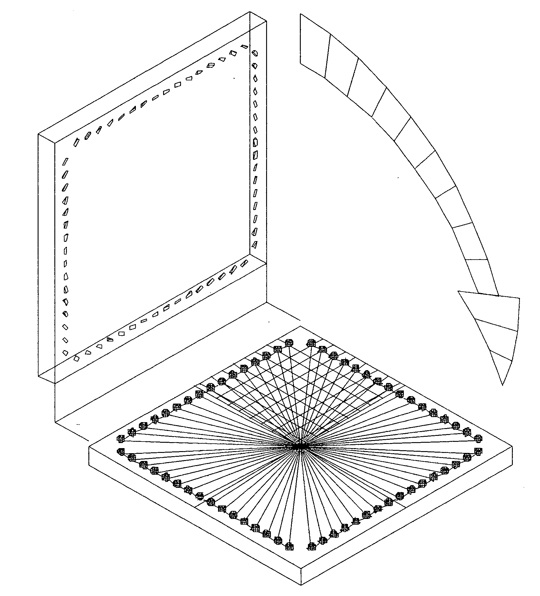
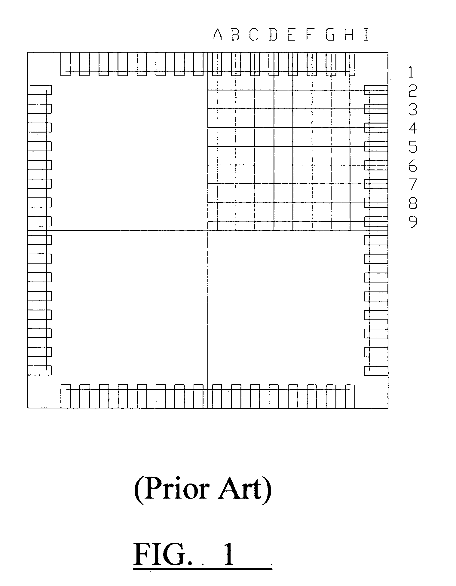
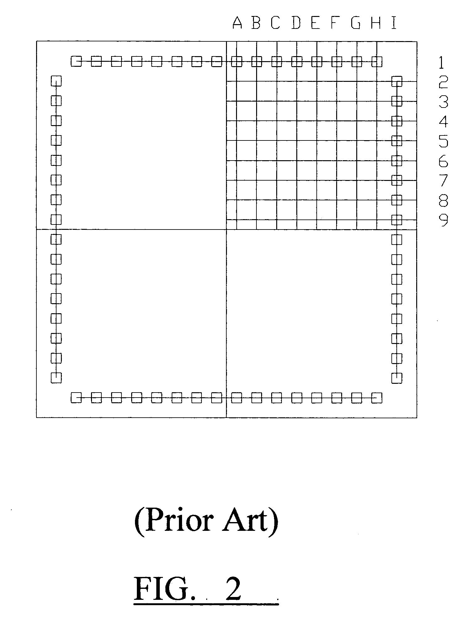
The invention discloses design concepts and means and methods that can be used for enhancing the reliability and extending the operating life of electronic devices, and assemblies incorporating such devices, and substrates and/or PCBs, especially if such assemblies are exposed to severe environments such as thermal cycling or power cycling. The main thrust of the invention is to provide flexible joints, such as columns, between the attached components, and preferably to orient such joints, so that they would present their softest bending direction towards the thermal center or fixation point of the assemblies. Joints with rectangular or elongated cross-section are preferred, and they should be oriented so that the wide face of each joint would be facing the thermal center, perpendicular to the thermal deformation ray emanating from the thermal center towards the center of each respective joint. The concepts apply equally to leadless packages as well as to leaded packages.

Description

[0001] This present application is a NON-PROVISIONAL UTILIY PATENT APPLICATION claiming the priority and benefits of the following six previous applications, which include four provisional patent applications and two non-provisional utility patent applications, all of which are incorporated herein in their entirety by reference:[0002] 1. Provisional Patent Application Serial No. 60 / 231,387, filed Sep. 8, 2000, entitled "Probers", which will be referred to as Ref1, and[0003] 2. Provisional Patent Application Serial No. 60 / 257,673, filed Dec. 22, 2000, entitled "Probes and Sockets", which will be referred to as Ref2, and[0004] 3. Provisional Patent Application Serial No. 60 / 268,467, filed Feb. 12, 2001, entitled "Probes, Sockets, Packages & Columns", which will be referred to as Ref3, and[0005] 4. Nonprovisional Utility patent application Ser. No. 09 / 947,240, filed Sep. 5, 2001, entitled[0006] 5. Nonprovisional Utility patent application Ser. No. 10 / 075,060, filed Feb. 11, 2002, entit...

Claims


Application Information

Patent Timeline
IPC IPC(8): B23K1/00H01L23/495H01L23/498H05K1/11H05K3/34
CPCB23K1/0016Y10T29/49117H01L23/49555H01L23/49816H01L23/49838H05K1/111H05K3/3426H05K3/3436H05K2201/09418H05K2201/09781H05K2201/10234H05K2201/10568H05K2201/10689H05K2201/10727H05K2201/2036H05K2203/0182H05K2203/0415H05K2203/0465H05K2203/048H05K2203/306B23K2201/40H01L2224/16H01L2924/00013H01L2224/29099B23K2101/40H01L2224/05568H01L2224/05573H01L2224/06135H01L2224/0614H01L2224/0615H01L2224/14144Y02P70/50H01L2224/05647H01L2924/00014
Inventor CHERIAN, GABE
Owner CHERIAN GABE
Why Eureka
Try Eureka