
Apparatus and method for sampling timing compensation in multi-carrier system

Active Publication Date: 2004-09-23
REALTEK SEMICON CORP
View PDF28 Cites 54 Cited by
  • Summary
  • Abstract
  • Description
  • Claims
  • Application Information

AI Technical Summary

Problems solved by technology

For a multi-carrier system, the synchronization error mainly results from sampling frequency offset and sampling phase error.
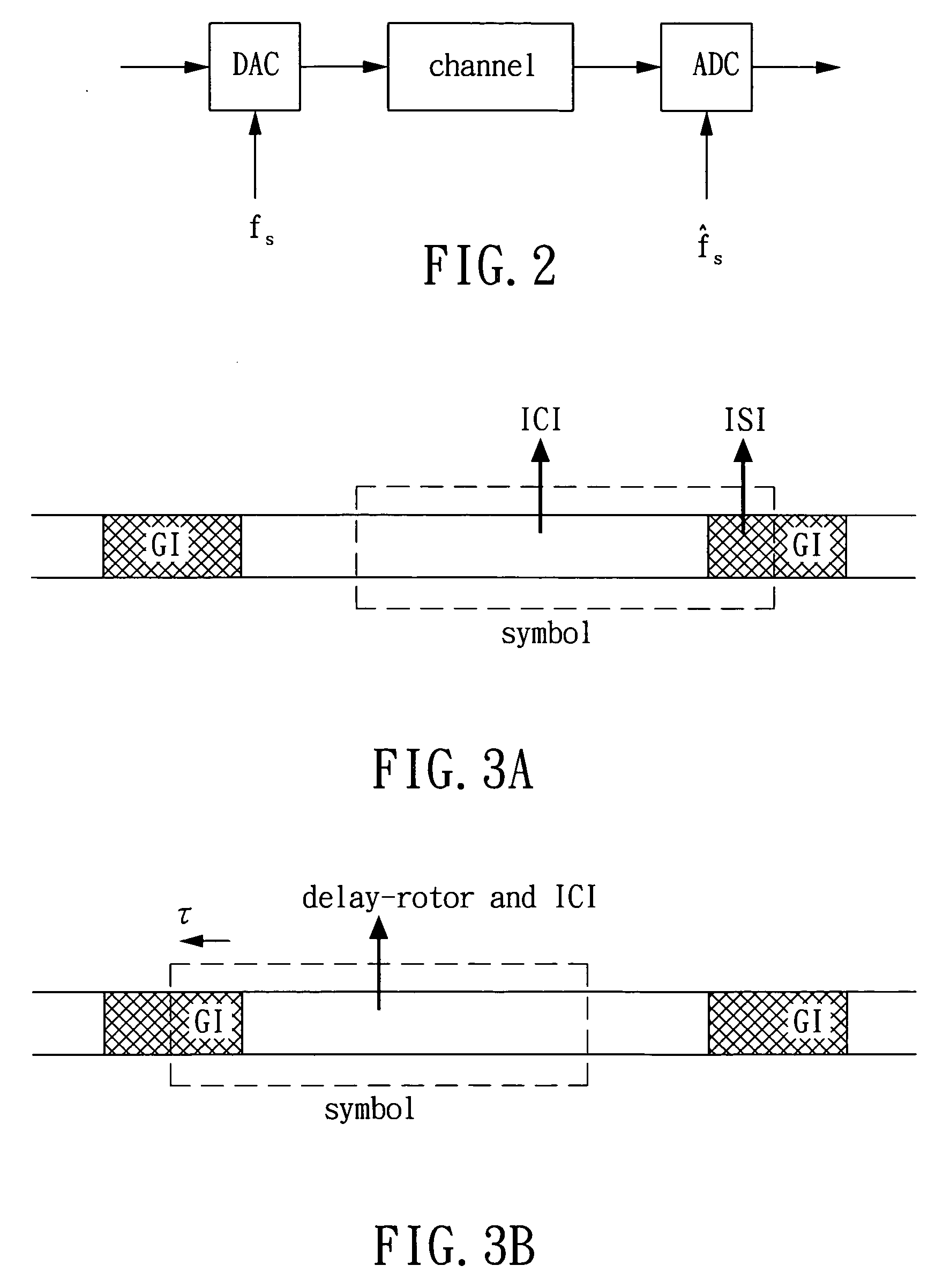
Besides the additional ICI and phase rotation, the sampling frequency offset would generate an accumulated sampling timing offset, which may cause ISI to degrade the system performance.

Method used


Image

  • Apparatus and method for sampling timing compensation in multi-carrier system
  • Apparatus and method for sampling timing compensation in multi-carrier system
  • Apparatus and method for sampling timing compensation in multi-carrier system

Examples


Embodiment Construction

[0019] The preferred embodiments of the present invention used in a multi-carrier system are described in detail below. FIG. 2 is a block diagram showing a multi-carrier system with a sampling frequency offset. In FIG. 2, since the sampling frequency f.sub.s=1 / T.sub.s of the DAC at the transmitter is not consistent with the sampling frequency {circumflex over (f)}.sub.s=1 / {circumflex over (T)}.sub.s of the ADC at the receiver, a sampling frequency offset .DELTA.f.sub.s=f.sub.s-{circumflex over (f)}.sub.s is generated. Here T.sub.s and {circumflex over (T)}.sub.s denote the sampling intervals of the transmitter and receiver respectively. Accordingly, the sampling interval of the receiver can be represented as

{circumflex over (T)}.sub.S=1 / (f.sub.s-.DELTA.f.sub.s)=T.sub.s / (1-.DELTA.)-.apprxeq.T.sub.s.multidot.(1+.DELTA.), where .DELTA.=.DELTA.f.sub.s / f.sub.-s=.DELTA.f.sub.sT.sub.s.

[0020] Due to the sampling frequency offset, a symbol boundary error is accumulated. Thus, the received si...


PUM


Abstract

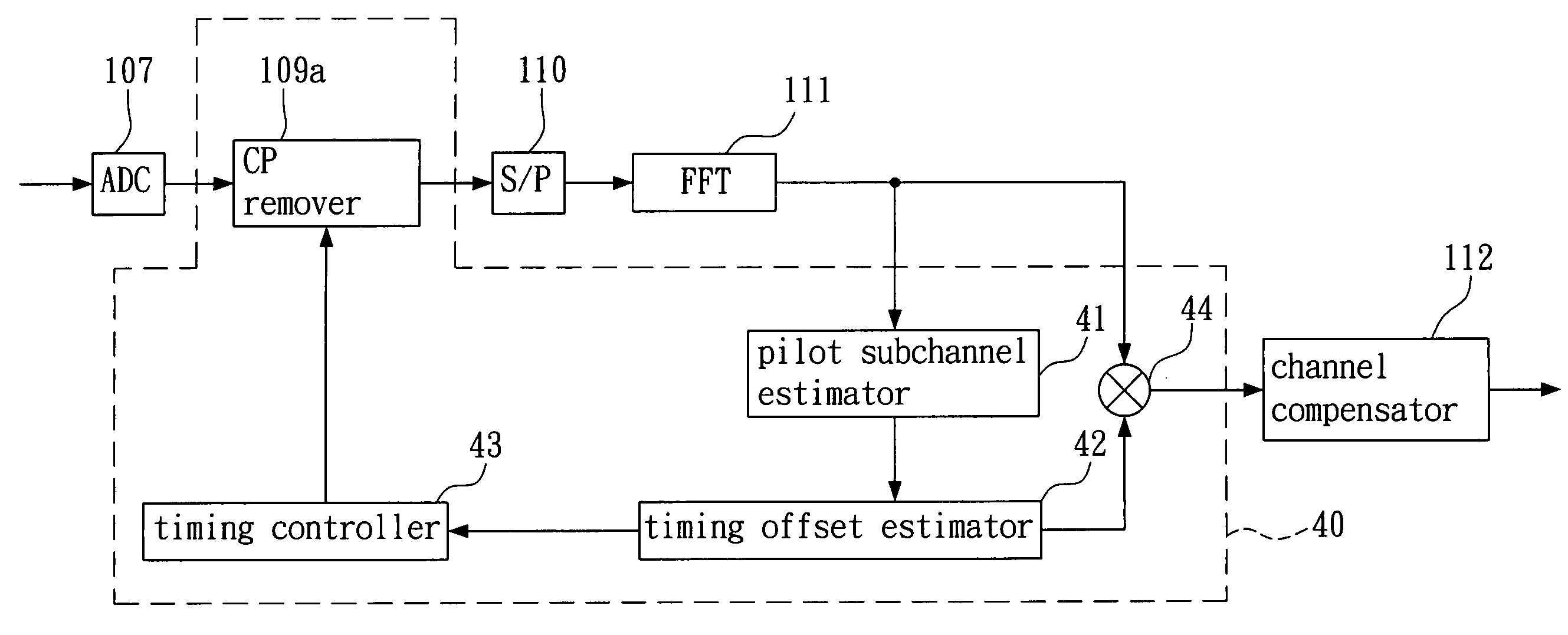
The present invention provides an apparatus and an associated method for sampling timing compensation, which can estimate sampling frequency offset between the receiver and transmitter of a multi-carrier system according to estimated frequency responses of two consecutive received symbols within each pilot subchannel, and compensate an accumulated sampling timing offset resulted from the sampling frequency offset. When the accumulated timing offset is not large, the apparatus uses a phase rotator to compensate with a corresponding accumulated phase rotation in frequency domain. When the accumulated timing offset is large, the apparatus first compensates with a specific timing offset in time domain, and then uses the phase rotator to compensate with a phase rotation corresponding to the remaining timing offset in frequency domain. A timing controller is used to compensate with the specific timing offset by adjusting a clock generator or a cyclic prefix remover of the receiver.

Description

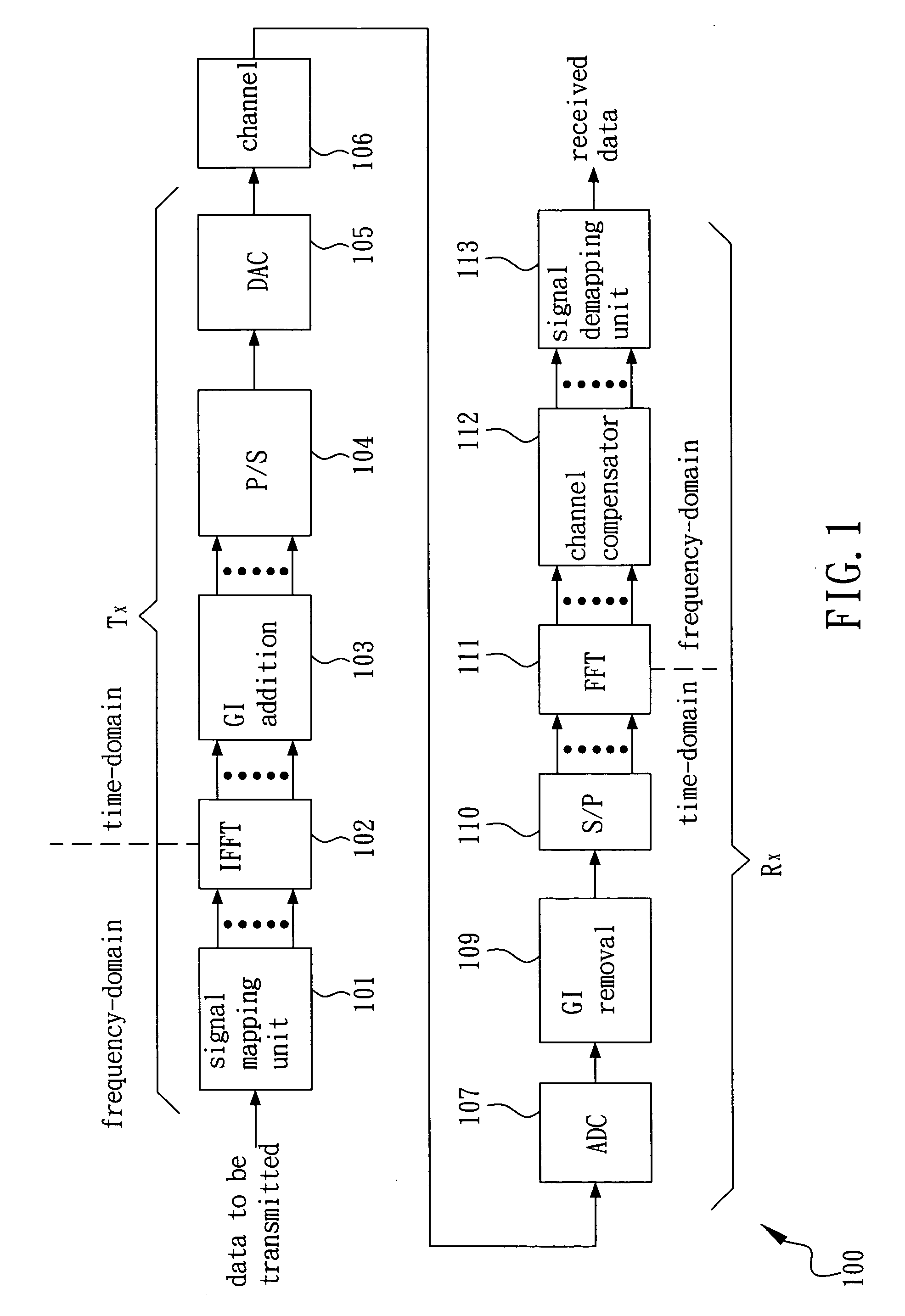
[0001] (a). Field of the Invention[0002] The present invention relates in general to a communication system, and more particularly to an apparatus for estimating and compensating sampling timing offset in a multi-carrier system and a method thereof.[0003] (b). Description of the Prior Arts[0004] In recent years, multi-carrier technology is widely applied to high-speed communication systems, such as asymmetric digital subscriber loop (ADSL), IEEE 802.11a / g wireless local area network (WLAN), etc. FIG. 1 is a block diagram of a typical multi-carrier system 100. The transmitter of the multi-carrier system 100 first distributes the data under transmission into N frequency-domain subchannels (N=2.sup.n, n is an integer) via a signal mapping unit 101, and maintains the orthogonality among the signals of each subchannel to prevent inter-carrier interference (ICI). Next, an inverse fast Fourier transform (IFFT) device 102 is used to transform the subchannel signals into time-domain signals,...

Claims


Application Information

Patent Timeline
IPC IPC(8): H03D1/00H04K1/10H04L27/26
CPCH04L27/2662H04L27/2675H04L27/2657
Inventor LIU, DER-ZHENGLIU, TAI-CHENGTUNG, SONG-NIENYEN, KUANG-YU
Owner REALTEK SEMICON CORP
Learn More