Control apparatus and method for friction device of vehicle

a technology of friction device and control apparatus, which is applied in the direction of vehicle position/course/altitude control, instruments, braking systems, etc., can solve the problems of difficult suppression or prevention of vibrations by conventional control apparatuses for vehicular friction devices, and the likelihood of vibrations called "judder"

Inactive Publication Date: 2004-09-23
TOYOTA JIDOSHA KK
View PDF5 Cites 38 Cited by
  • Summary
  • Abstract
  • Description
  • Claims
  • Application Information

AI Technical Summary

Benefits of technology

[0008] To accomplish the above and / or other object(s), there is provided according to one aspect of the invention a control apparatus for controlling an engagement pressure of a friction device of a vehicle that is disposed in a power transmission path of the vehicle and is adapted to be engaged when the vehicle is started, comprising a controller that controls the engagement pressure of the friction device so as to eliminate a pulsation component contained in variations in an engagement torque of the friction device.
[0009] The control apparatus as described above controls the engagement pressure of the friction device disposed in the power transmission path of the vehicle and adapted to be engaged upon a start of the vehicle so as to eliminate a pulsation component contained in variations in the engagement torque of the friction device. Thus, the control apparatus is able to settle or converge the pulsation component caused by stick slip of the friction material by, for example, increasing or reducing a squeeze load applied to the friction device, thereby preventing occurrence of judder. Consequently, the control apparatus is able to suppress occurrence of vibrations when the vehicle is started.
[0010] In a preferred embodiment of the invention, the control apparatus includes (a) an input rotational speed variation calculating unit that calculates variations in an input rotational speed of a transmission provided in the power transmission path, (b) a pulsation component calculating unit that calculates a pulsation component contained in the variations in the input rotational speed calculated by the input rotational speed variation calculating unit, and (c) an engagement pressure control unit that controls the engagement pressure of the friction device so as to eliminate the pulsation component calculated by the pulsation component calculating unit. Thus, a practical control apparatus for a vehicular friction device can be provided which is simply constructed to monitor variations in the input rotational speed of the transmission corresponding to variations in the engagement torque of the friction device.
[0011] In another preferred embodiment of the invention, the control apparatus includes (a) an input torque variation calculating unit that calculates variations in an input torque of a transmission provided in the power transmission path, (b) a pulsation component calculating unit that calculates a pulsation component contained in the variations in the input torque calculated by the input torque variation calculating unit, and (c) an engagement pressure control unit that controls the engagement pressure of the friction device so as to eliminate the pulsation component calculated by the pulsation component calculating unit. Thus, a practical control apparatus for a vehicular friction device can be provided which is simply constructed to monitor variations in the input torque of the transmission corresponding to variations in the engagement torque of the friction device.
[0012] In a further preferred embodiment, the engagement pressure control unit calculates a squeeze load containing a pulsation component having a phase opposite to that of the pulsation component calculated by the pulsation component calculating unit, and controls the engagement pressure of the friction device based on the calculated squeeze load. With this arrangement, the control apparatus is able to cancel the pulsation component caused by to stick slip of the friction material of the starting friction device, through control of the squeeze load, and is thus able to efficiently suppress occurrence of vibrations upon a star of the vehicle.

Problems solved by technology

In the meantime, it is known that, when a friction device provided in a power transmission path for starting the vehicle is engaged upon a start of the vehicle, vibrations called "judder" are likely to occur due to stick slip (or intermittent slip) caused by misalignment or material characteristics of friction members of the friction device.
While the vibrations, which make the driver uncomfortable, are desired to eliminate, it has been difficult for conventional control apparatuses for vehicular friction devices to suppress or prevent occurrence of the vibrations.

Method used


Image

  • Control apparatus and method for friction device of vehicle
  • Control apparatus and method for friction device of vehicle
  • Control apparatus and method for friction device of vehicle

Examples


Embodiment Construction

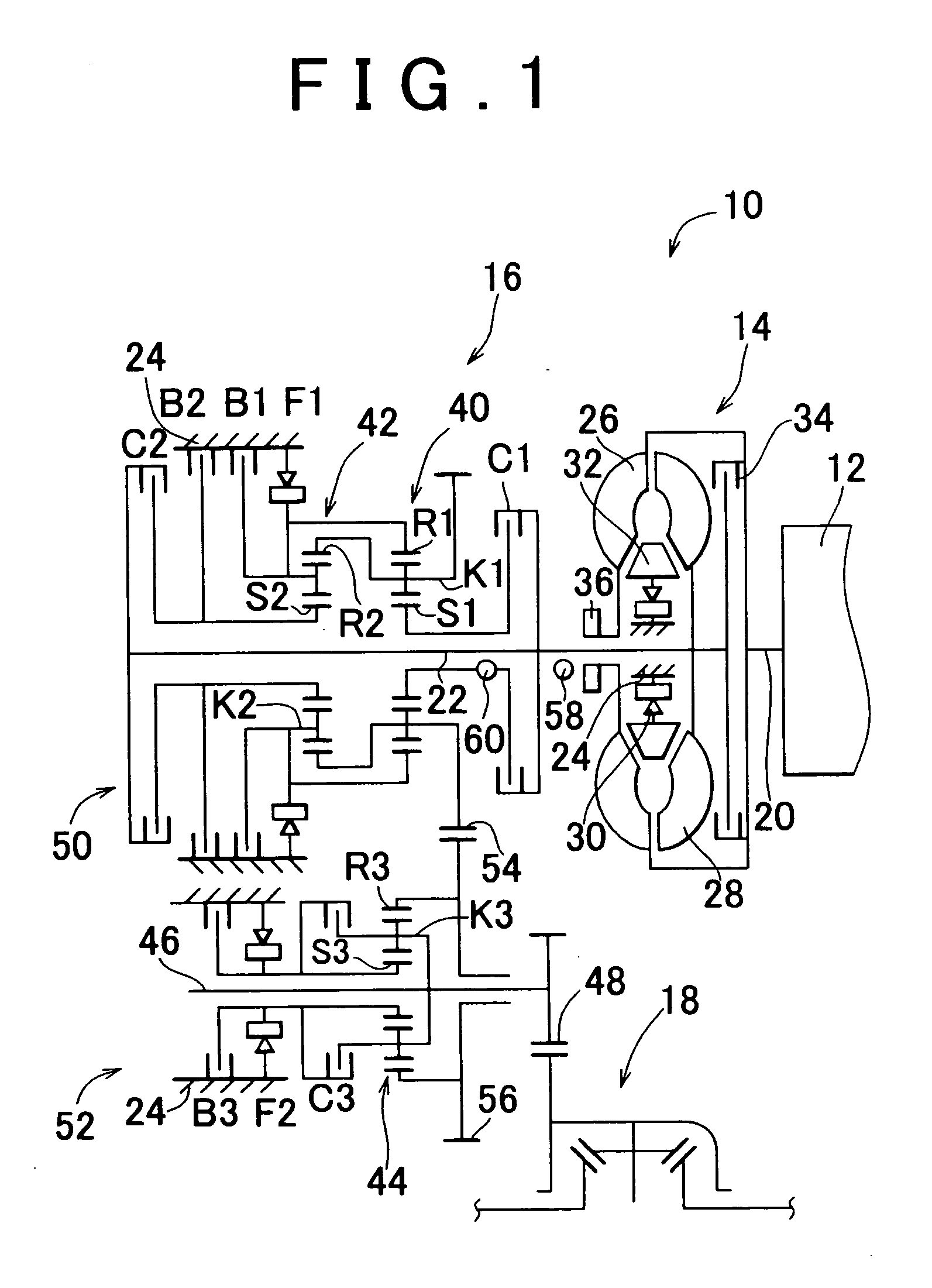
[0022] An exemplary embodiment of the invention will be described in detail with reference to the drawings. FIG. 1 schematically shows one example of a power transmitting system 10 of a FF (front engine front drive) vehicle, which employs a control apparatus according to one embodiment of the invention. In the power transmitting system 10, driving force or power generated by an engine 12 as a power source is transmitted to driving wheels (front wheels) (not shown), via a torque converter 14, an automatic transmission 16, and a differential gear unit 18. The torque converter 14 includes a pump impeller 26 coupled to a crankshaft 20 of the engine 12, a turbine wheel 28 coupled to an input shaft 22 of the automatic transmission 16, a stator 32 fixed to a housing 24 as a stationary member via a one-way clutch 30, and a lock-up clutch 34 that directly connects the crankshaft 20 with the input shaft 22. The lock-up clutch 34 is a hydraulic friction device, which is frictionally engaged wh...


PUM


Abstract

A control apparatus for a friction device of a vehicle that is disposed in a power transmission path of the vehicle and is adapted to be engaged upon a start of the vehicle is provided. The control apparatus controls the engagement pressure of the friction device so as to eliminate a pulsation component contained in variations in an engagement torque of the friction device.

Description

INCORPORATION BY REFERENCE[0001] The disclosure of Japanese Patent Application No. 2003-072718 filed on Mar. 17, 2003, including the specification, drawings and abstract, is incorporated herein by reference in its entirety.[0002] 1. Field of the Invention[0003] The invention generally relates to an apparatus and a method for controlling a friction device provided in a vehicle and used for starting the vehicle, and, more particularly, to a technique for suppressing or preventing occurrence of vibrations due to stick slip of a friction material of the friction device.[0004] 2. Description of Related Art[0005] Generally, a transmission provided in a power transmission path of a vehicle includes a plurality of friction devices, such as hydraulic clutches and brakes, and establishes a selected one of gear stages or speeds by selectively engaging the friction devices. Various control apparatuses for controlling the engaging states of such friction devices have been proposed. For example, ...

Claims


Application Information

Patent Timeline
Patent Type & Authority Applications(United States)
IPC IPC(8): B60T1/06B60T7/12F16D65/00F16H61/06
CPCB60T1/062F16H2061/0462F16D65/0012F16D2500/1026F16D2500/1045F16D2500/1087F16D2500/30412F16D2500/30415F16D2500/50224F16D2500/50293F16D2500/70404F16D2500/7044F16H61/061F16H61/686F16H2312/02B60T7/122
Inventor KOHNO, TETSUYAYASUDA, YUJI
Owner TOYOTA JIDOSHA KK
Why Eureka
Try Eureka