

Motor controller, semiconductor integrated circuit, indicating instrument and method for controlling a motor
- Summary
- Abstract
- Description
- Claims
- Application Information
AI Technical Summary
Problems solved by technology
Method used
Image

Examples
first embodiment
[0027] (First Embodiment)
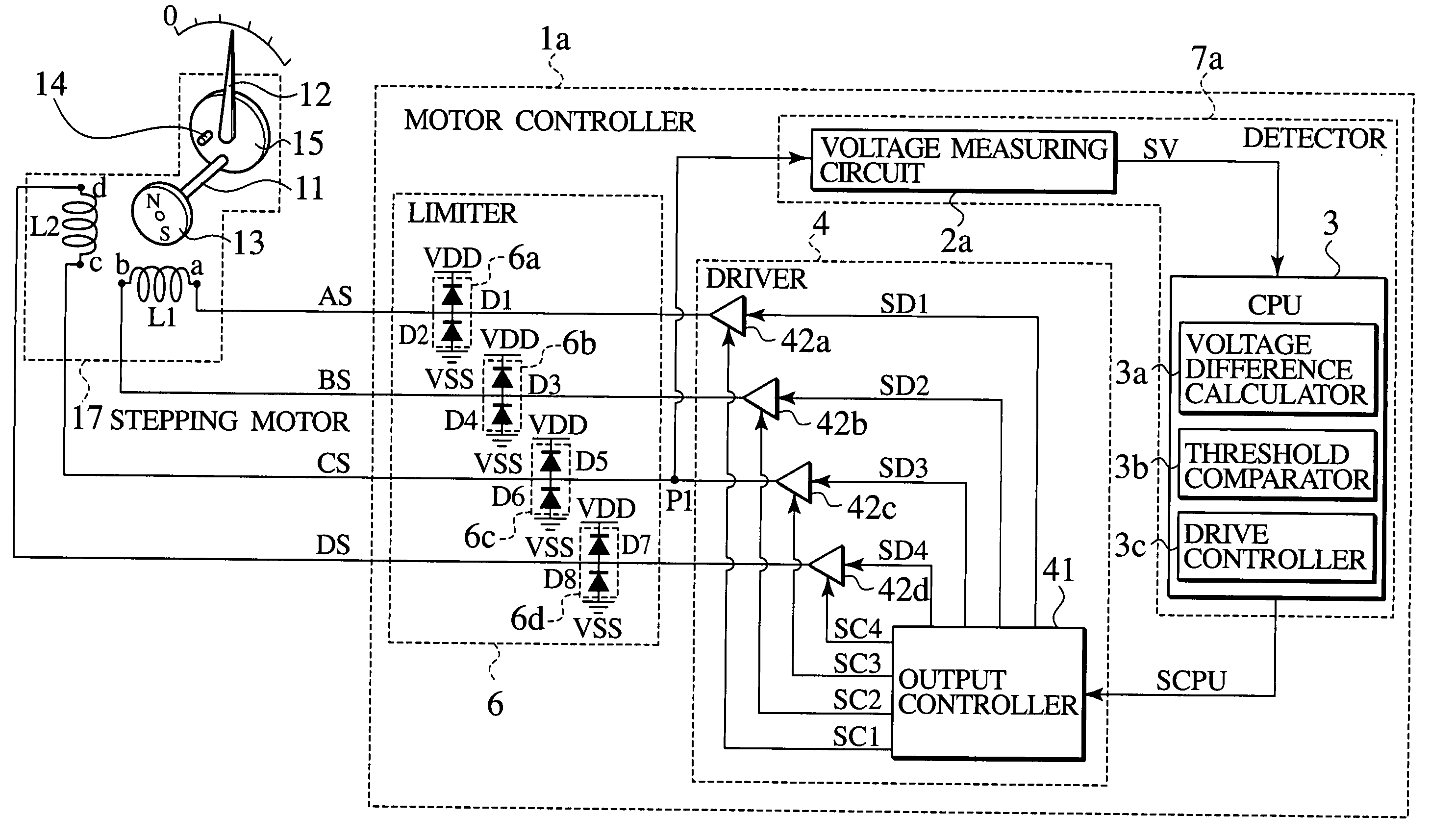
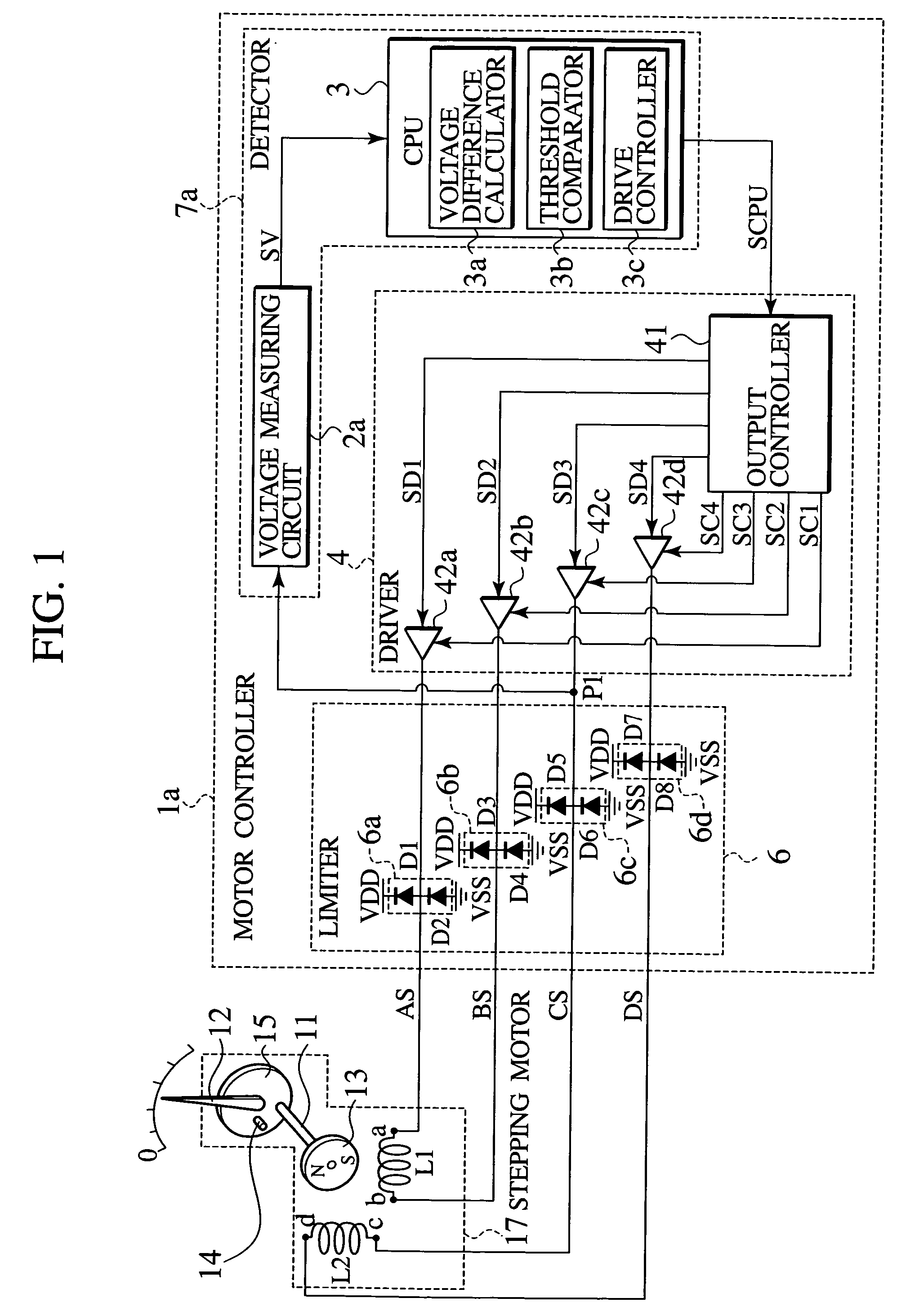
[0028] As shown in FIG. 1, an indicating instrument according to a first embodiment of the present invention includes a stepping motor 17, a pointer 12 rotatively driven by the stepping motor 17, and a motor controller 1a connected to the stepping motor 17. The motor controller 1a includes a limiter 6 connected to the stepping motor 17, a driver 4 connected to the limiter 6, and a detector 7a connected between the driver 4 and a node P1 disposed between the limiter 6 and the driver 4. The detector 7a performs a difference processing for information relating to a counter electromotive force and induced electromotive force, which are generated by the stepping motor 17. The detector 7a generates a driving control signal SCPU based on a result of the difference processing. The driver 4 drives the stepping motor 17 based on the driving control signal SCPU. The limiter 6 controls the counter electromotive force generated by the stepping motor 17. Note that the "co...
second embodiment
[0045] (Second Embodiment)
[0046] An indicating instrument according to a second embodiment of the present invention differs from the motor controller la shown in FIG. 1 in that a timer 5 is connected to the CPU 31 in parallel with the voltage measuring circuit 2b as shown in FIG. 6. The timer 5 measures the duration of the counter electromotive force. A second threshold Tth is further set in the threshold comparator 31b of the CPU 31. The indicating instrument according to the second embodiment has the same constitution as that of the indicating instrument shown in FIG. 1 except for the provision of the timer 5. As shown in FIG. 7, the motor controller 1b shown in FIG. 6 can be constituted as a semiconductor integrated circuit 91b by monolithically integrating the constituent components of the motor controller 1b on a semiconductor chip 90b.
[0047] Next, a method for controlling a motor according to the second embodiment of the present invention will be described by use of FIGS. 3, 4...
third embodiment
[0054] (Third Embodiment)
[0055] An indicating instrument according to a third embodiment of the present invention differs from the CPU 3 shown in FIG. 1 in that CPU 32 shown in FIG. 9 includes a drive angle determination circuit 32d configured to judge a drive angle at which the stepping motor 17 should be driven. The detector 7c is connected to outputs of the first buffer 42a, the second buffer 42b, the third buffer 42c, and fourth buffer 42d. The timer 51 is connected to the CPU 32 in parallel with the voltage measuring circuit 2c. The indicating instrument according to the third embodiment has the same constitution as that of the indicating instruments shown in FIG. 1 and FIG. 6 except for the provision of the drive angle determination circuit 32d. As shown in FIG. 10, the motor controller 1c shown in FIG. 9 can be constituted as a semiconductor integrated circuit 91c by monolithically integrating the constituent components of the motor controller 1c on a semiconductor chip 90c.
[...
PUM
 Abstract
Description
Claims
Application Information