Linear Amplification by synchronized chaotic oscillation

a technology of synchronized chaotic oscillation and linear amplification, applied in the direction of antennas, noise generation, electric long antennas, etc., can solve the problems of conventional design philosophy, interference between, and degrade the signal, and achieve the effect of maximizing the power added efficiency of the amplifier

Inactive Publication Date: 2004-09-30
GLENN CHANCE MICHAEL SR +1
View PDF3 Cites 19 Cited by
  • Summary
  • Abstract
  • Description
  • Claims
  • Application Information

AI Technical Summary

Benefits of technology

[0008] The present apparatus and methods advances the art and provides functions, aspects and features which include, for example, substantially eliminating the inherent linearity-efficiency tradeoff of existing amplifier circuits, and removing the requirement for, and the constraints imposed by, prior art design methodologies, structures and implementations of linear amplifies.
[0016] Another objective obtained with an amplifier in accordance with this description is the elimination of the conventional amplifier requirement of selecting active circuit elements, and biasing such elements, to operate within the elements' linear regions.

Problems solved by technology

The harmonics degrade the signal and cause interference between signals occupying proximal bands of the frequency spectrum.
This conventional design philosophy, however, faces at least one well-known dilemma.
This dilemma is that biasing and interconnecting transistors to obtain a more linear transfer function typically lowers the efficiency of the amplifier.
For example, the traveling wave tubes (TWTs) in satellites must be operated in a nonlinear mode, otherwise the efficiency is too poor for the overall system to be cost effective.
This incurs a performance cost, as the signal constellations generated by TWTs are severely distorted.
This poses substantial problems because communication signal theory, and its practical implementation in existing technology, is largely a linear art.
Most communication systems, such as cellular telephones, cannot tolerate the signal degradation and out-of-band interference that would result from employing non-linear transistor modes.

Method used


Image

  • Linear Amplification by synchronized chaotic oscillation
  • Linear Amplification by synchronized chaotic oscillation
  • Linear Amplification by synchronized chaotic oscillation

Examples


Embodiment Construction

[0008] The present apparatus and methods advances the art and provides functions, aspects and features which include, for example, substantially eliminating the inherent linearity-efficiency tradeoff of existing amplifier circuits, and removing the requirement for, and the constraints imposed by, prior art design methodologies, structures and implementations of linear amplifies.

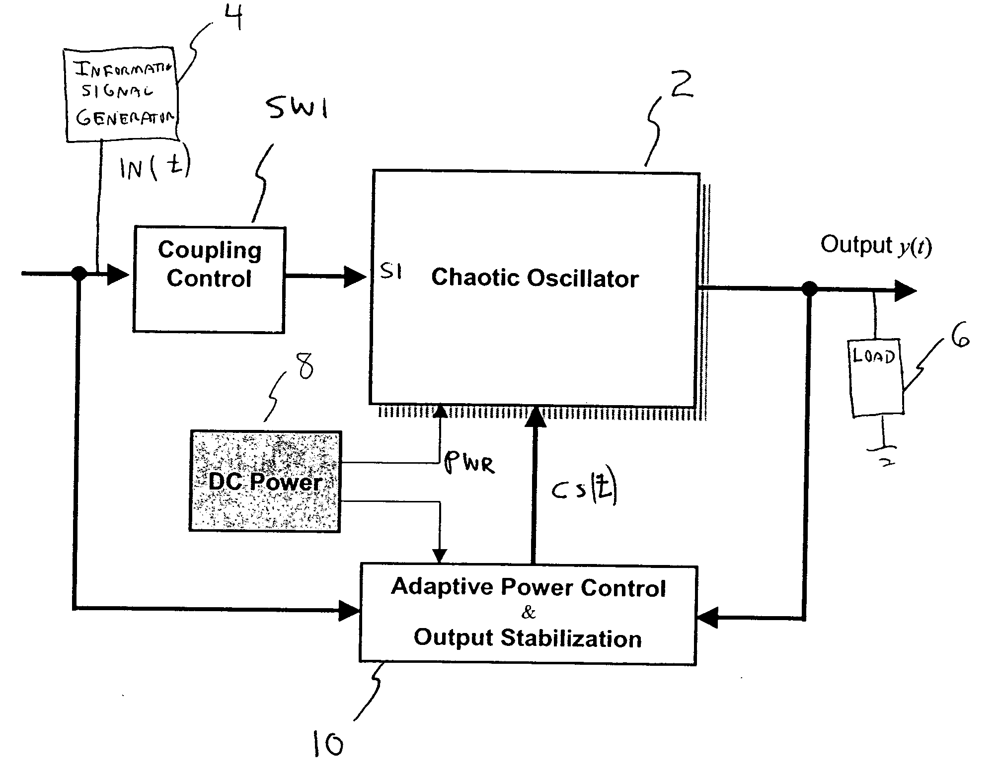
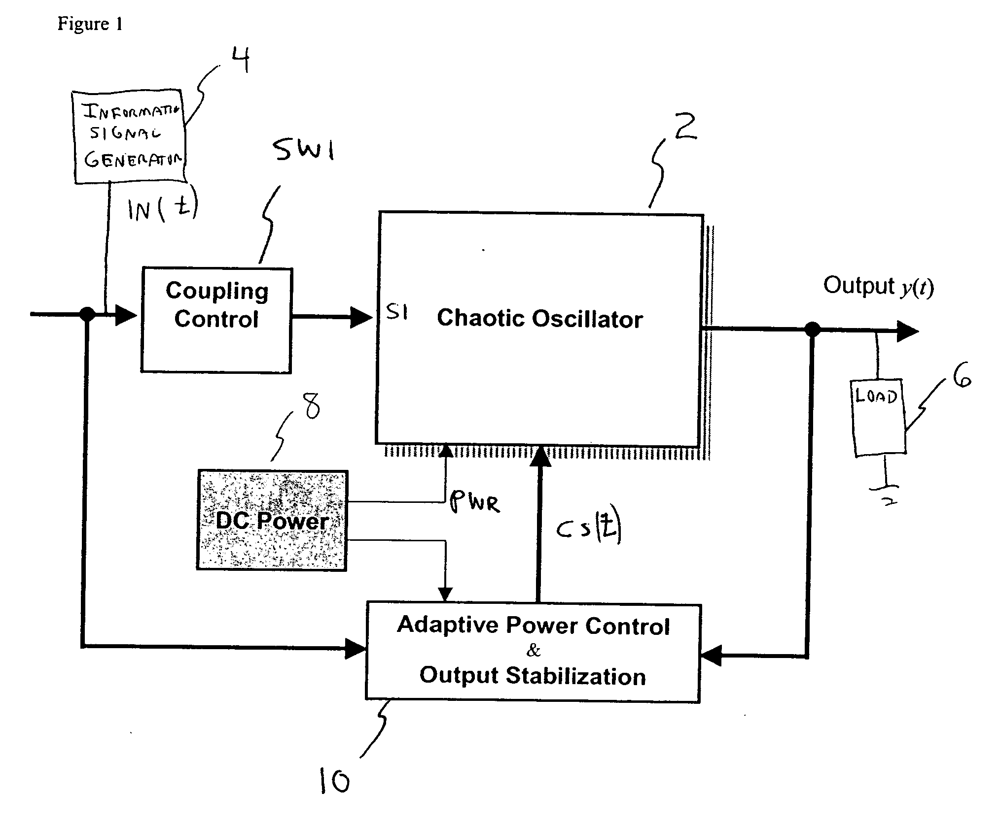
[0009] An example embodiment includes a power supply, and a chaotic oscillator power circuit connected to the power supply. The chaotic oscillator power circuit includes a coupling element for receiving an externally generated information signal. A load is connected to, or is an element within, the chaotic oscillator power circuit. The power chaotic circuit and the receiving terminal are arranged and constructed such that, concurrent with the information signal delivered to the receiving terminal being switched off or below a predetermined input voltage envelope, the energy state of the powered element oscill...


PUM


Abstract

An amplifier for arbitrary waveforms, including a chaotic oscillator circuit having a coupling element for receiving an information signal. A load is connected to the chaotic oscillator circuit. The oscillation of the chaotic oscillator circuit synchronizes to the information signal and delivers an output signal substantially identical to the information signal and dissipates a power in the load amplified with respect to the information signal. The chaotic oscillator optionally uses an active element such that when synchronized it is in a non-linear operating region. Optionally, the error between the information signal and output voltage is minimized by controlling the volume of the chaotic oscillator in response to the error.

Description

[0001] The present invention relates to the amplification of electronic signals and, more particularly, to linear amplification of signals having arbitrary waveforms by synchronization of a chaotic oscillator.DESCRIPTION OF THE BACKGROUND[0002] In the electrical and telecommunication arts, amplifiers are devices that receive an electrical signal having a first power and output, signal of the same waveform as the input, but at a significantly higher current and, therefore, capable of delivering a power significantly higher than the first power. Early amplifiers used vacuum tubes as a basic building block, each tube acting as an electric current valve, by using a low power signal to control a much higher electric power flow between the tube's anode and cathode. Ideally, the current flowing between the anode and the cathode is perfectly proportional to the control signal. In other words, for most applications a sought-after transfer function for a vacuum tube is linear, the output bein...

Claims


Application Information

Patent Timeline
Patent Type & Authority Applications(United States)
IPC IPC(8): H03B29/00
CPCH03B29/00
Inventor GLENN, CHANCE MICHAEL SR.HAYES, SCOTT T.
Owner GLENN CHANCE MICHAEL SR
Why Eureka
Try Eureka