Storage device

a storage device and storage technology, applied in the field of storage devices, can solve the problems of system configuration, difficult to simplify the system management, and difficulty in maintaining the system,

Inactive Publication Date: 2004-09-30
HITACHI LTD
View PDF56 Cites 138 Cited by
  • Summary
  • Abstract
  • Description
  • Claims
  • Application Information

AI Technical Summary

Benefits of technology

0024] FIG. 5 is a diagram of an example of programs stored in a file system control memory.
0025] FIG. 6 is a diagram of an example of programs stored in a disk array control memory.

Problems solved by technology

The first set of problems entailed in the prior art is that there is a high dependency on the computer connected to the storage device, that there is a limitation in the system configuration, and that it is difficult to simplify the system management.
However, when the system configuration is altered, such as when an old computer is replaced by a new computer, maintaining the system can be difficult due to such reasons as the system configuration of the new computer not being able to take over the software's control information.
As a result, it would be difficult for a plurality of computers to share the same logical storage devices, and integrating storage devices used by a plurality of computers in order to reduce the management cost of the computer system would require imposing certain limitations on the configuration of the computer system, such as allocating a logical storage device for each computer.
The second problem is that optimal placement of data according to the life cycle or type of data is difficult.
However, there are no technologies disclosed for determining storage regions in which to store data by taking into consideration differences in data properties that are dependent on the data's life cycle stage, i.e., the time elapsed since the corresponding file was generated, the type of application that generates and uses the data, and the type of data itself.
The third problem is that the effect of the hierarchical storage control is small.
Although the conventional system described above executes a hierarchical storage control by taking advantage of the difference in capacity and price between magnetic tapes and magnetic disks, the difference in capacity and price between magnetic tapes and magnetic disks have been growing smaller in recent years; consequently, the effect of cost optimization and cost reduction through the use of hierarchical storage control has also been growing smaller.
Furthermore, due to the fact that the access speed to magnetic tapes is extremely slow compared to access speed to magnetic disks, it is difficult to use magnetic tapes as storage device for online access.

Method used


Image

  • Storage device
  • Storage device
  • Storage device

Examples


embodiment 1

[0040] (1) Example of System Configuration (FIG. 1)

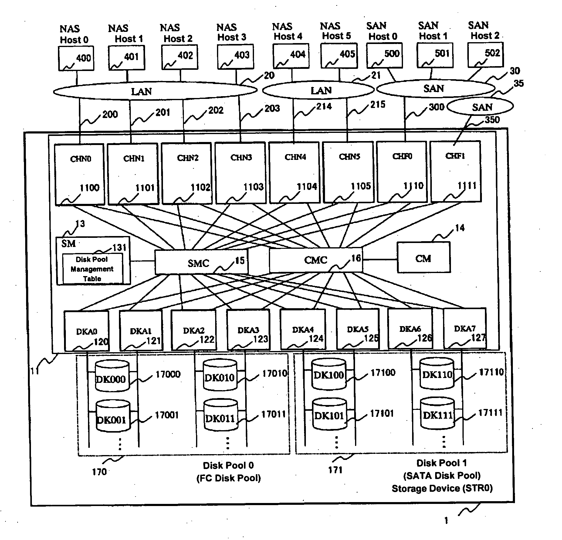
[0041] FIG. 1 is a diagram indicating an example of a computer system including a storage device 1 (it is also called a storage system), to which the present invention is applied. In the following, x may be any integer.

[0042] The storage device 1 is a disk array system comprising a disk controller (hereinafter called "DKC") 11 and a plurality of magnetic disk devices (hereinafter simply called "disks") 170x and 171x. In the present embodiment, the storage device 1 is provided with two types of disks 170xand 171x. 170x are Fibre Channel (hereinafter called "FC") disks with FC-type interface, while 171x are serial AT attached (hereinafter called "SATA") disks with serial ATA-type (SATA-type) interface. A plurality of FC disks 170x makes up an FC disk pool 0 (170), while a plurality of SATA disks 171x makes up a SATA disk pool 1 (171). The disk pools will be described in detail later.

[0043] Next, the configuration of the DKC 11 of the ...

embodiment 2

[0155] (1) Example of System Configuration (FIG. 13)

[0156] Next, referring to FIG. 13, an example of the system configuration of the second embodiment will be described. In the present embodiment, a hierarchical storage control is executed between storage devices in a system in which a storage device 1 (hereinafter called "STR0") described in the first embodiment and another storage device 1a (hereinafter called "STR1") are connected via a network.

[0157] In FIG. 13, the storage device STR1 (1a) is the other storage device connected to the storage device STR0 (1) via a LAN 20; otherwise, the system (configuration components are the same as in FIG. 1.

[0158] In the STR1 (1a), an NCTL0 (1100a) and an NCTL1 (1101a) are NAS controllers, and a disk pool 0 (170a) is a disk pool connected to the NCTL0 and NCTL1.

[0159] Instead of the SM I / F control circuit 11005 and the CM I / F control circuit 11006 in the configuration of the CHN 1100 according to the first embodiment shown in FIG. 4, the NAS...

embodiment 3

[0188] (1) Example of System Configuration (FIG. 14)

[0189] Next, with reference to FIG. 14, an example of the system configuration according to the third embodiment will be described. In the present embodiment, as in the second embodiment, a hierarchical storage control is executed among storage devices in a system in which another storage device STR2 (1b) is connected to a storage device STR0 (1) via a network. The third embodiment differs from the second embodiment in that while the network that connects the storage devices was the LAN 20 and file I / O interfaces were used between storage devices in the second embodiment, the network that connects the storage devices is a SAN 35, which is a dedicated network for connection between the storage devices, and a block I / O interface is used between storage devices in the third embodiment.

[0190] In FIG. 14, the storage device STR2 (1b) is a storage device with a small-scale configuration similar to the storage device STR1 (1a) in the seco...


PUM

PropertyMeasurementUnit
speedaaaaaaaaaa
access frequencyaaaaaaaaaa
frequencyaaaaaaaaaa

Abstract

A storage device is provided with a file I/O interface control device and a plurality of disk pools. The file I/O interface control device sets one of a plurality of storage hierarchies defining storage classes, respectively, for each of LUs within the disk pools, thereby forming a file system in each of the LUs. The file I/O interface control device migrates at least one of the files from one of the LUs to another one of the LUs of an optimal storage class, based on static properties and dynamic properties of each file.

Description

[0001] 1. Field of the Invention[0002] The present invention relates to a storage device used in a computer system.[0003] 2. Related Background Art[0004] In a conventional system, a high-speed storage device and a low-speed storage device may be connected to a computer called a hierarchical storage. In the system, files that are frequently used are stored in the high-speed storage device such as a magnetic disk device, while files that are not frequently used are stored in the inexpensive, low-speed storage device such as a tape device. Which files should be placed, i.e., stored, in which storage device is determined by using a table that manages access frequency of each file.[0005] In another conventional system, a plurality of logical storage devices having different processing speeds and storage capacities are configured within a storage device that is connected to a computer and used. Such a system may be represented by disk array subsystems. In this system, the storage device m...

Claims


Application Information

Patent Timeline
Patent Type & Authority Applications(United States)
IPC IPC(8): G06F3/06G06F3/00G06F7/00G06F12/00G06F17/30G11B20/10G11B20/12
CPCG06F3/0608G06F3/061G06F3/0649Y10S707/99955G06F17/30067Y10S707/99953G06F3/0685G06F16/10
Inventor MATSUNAMI, NAOTOSONODA, KOJIYAMAMOTO, AKIRANOZAWA, MASAFUMIIWASAKI, MASAAKI
Owner HITACHI LTD
Why Eureka
Try Eureka