Carbon nanotube heat-exchange systems

a heat exchange system and carbon nanotube technology, applied in indirect heat exchangers, electrochemical generators, lighting and heating apparatuses, etc., can solve the problems of large heat exchange system, and large cumbersomeness

Inactive Publication Date: 2004-10-07
ALLIANCE FOR SUSTAINABLE ENERGY
View PDF18 Cites 132 Cited by
  • Summary
  • Abstract
  • Description
  • Claims
  • Application Information

AI Technical Summary

Benefits of technology

0011] FIG. 1 is a high-level diagram illustrating a cooling system in which...

Problems solved by technology

However, these materials make the heat-exchange systems heavy, which negatively impacts the automobile's performance, fuel consumption, and emissions.
These loading requirements increase the surface area that must be exposed to the air flow, making the heat-exchange system large and cumbersome.
Consequently, these loading requirements also increase drag on the autom...

Method used


Image

  • Carbon nanotube heat-exchange systems
  • Carbon nanotube heat-exchange systems
  • Carbon nanotube heat-exchange systems

Examples


Embodiment Construction

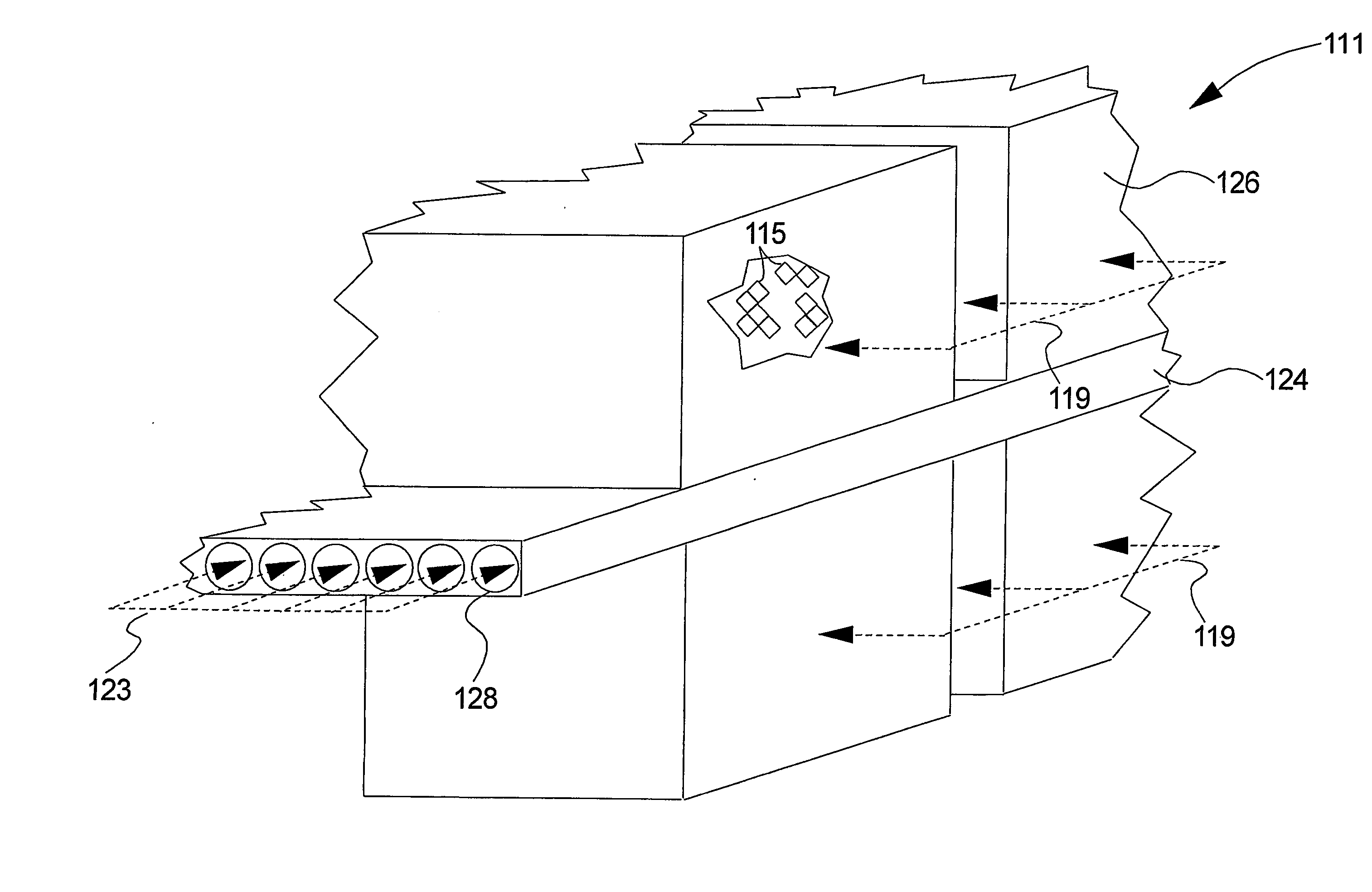
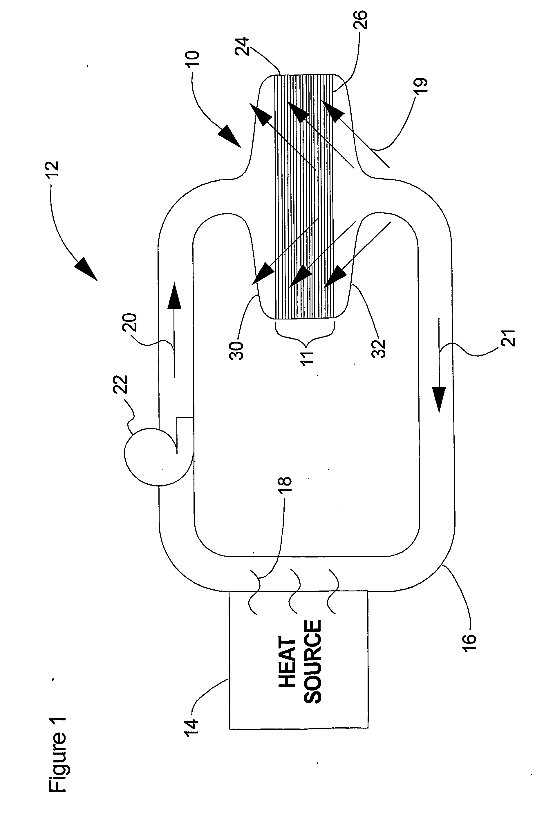
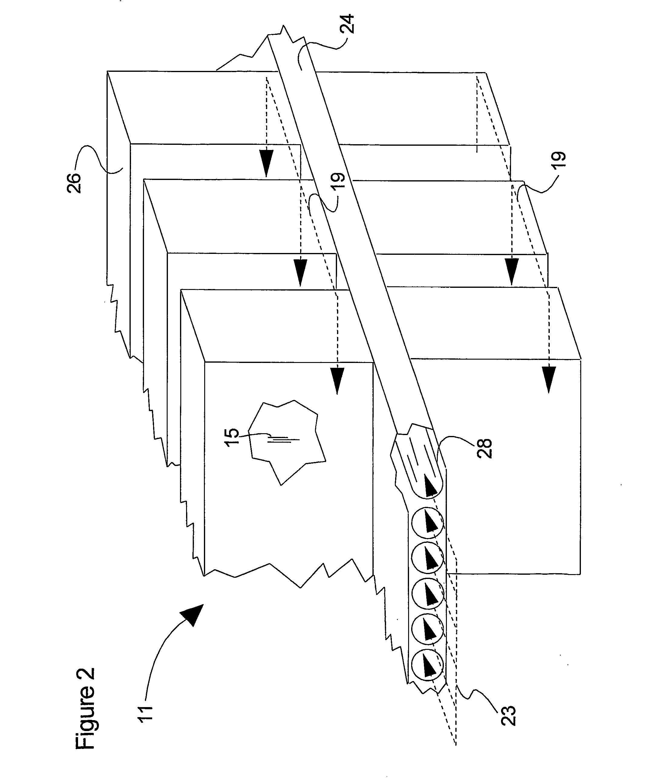
[0017] Carbon nanotube heat-exchange system 10 (FIG. 1) and method for producing the same is shown and described as it may be used in a cooling system 12 according to preferred embodiments of the invention. Briefly, heat-exchange systems 10 dissipate heat produced at a heat source 14 (e.g., an internal combustion engine). A cooling fluid may be circulated through a coolant loop 16 in and / or around the heat source 14 so that the fluid absorbs heat from the heat source 14. The heat-exchange system 10 is provided in thermal contact with the fluid circulating through the coolant loop 16 and with an external medium 19 (e.g., air). As the cooling fluid flows through the heat-exchange system 10, heat is transferred from the cooling fluid to the external medium. The cooling fluid may then be recirculated through the cooling loop 16 or discharged to the environment. Alternatively, the heat-exchange system 10 of the present invention may be provided in direct contact with the heat source 14, ...


PUM


Abstract

A carbon nanotube heat-exchange system (10) and method for producing the same. One embodiment of the carbon nanotube heat-exchange system (10) comprises a microchannel structure (24) having an inlet end (30) and an outlet end (32), the inlet end (30) providing a cooling fluid into the microchannel structure (24) and the outlet end (32) discharging the cooling fluid from the microchannel structure (24). At least one flow path (28) is defined in the microchannel structure (24), fluidically connecting the inlet end (30) to the outlet end (32) of the microchannel structure (24). A carbon nanotube structure (26) is provided in thermal contact with the microchannel structure (24), the carbon nanotube structure (26) receiving heat from the cooling fluid in the microchannel structure (24) and dissipating the heat into an external medium (19).

Description

[0002] This invention relates to heat-exchange systems and more specifically to carbon nanotube heat-exchange systems.[0003] Most power-generation systems produce heat as a by-product. For example, internal combustion engines used to power most vehicles today combust a high-energy fuel (e.g., gasoline) to generate mechanical motion and heat. Fuel cells that convert hydrogen and oxygen into electricity and heat are also being developed for a variety of applications, including power production for vehicles and electrical appliances. Other power-generation systems, such as bio-fuel processing, petroleum refining, industrial processing, and solar-thermal systems, to name a few, also produce heat as a by-product. At least some of the heat produced by such power-generation systems must be dissipated to the ambient environment.[0004] Various cooling systems have been developed for dissipating heat. Automobiles, for example, may have as many as fourteen separate cooling systems, including c...

Claims


Application Information

Patent Timeline
IPC IPC(8): F28D1/02F28F1/12F28F13/00F28F13/18F28F21/02
CPCF28D1/0246F28F1/12F28F13/003F28F13/185F28F21/02F28F2260/02F28D15/0233Y10S165/905
Inventor HENDRICKS, TERRY JOSEPHHEBEN, MICHAEL J.
Owner ALLIANCE FOR SUSTAINABLE ENERGY
Why Eureka
Try Eureka