Projector

a projector and projector technology, applied in the field of projectors, can solve the problems of reducing brightness, deteriorating picture quality, and reducing the illuminance ratio,

Active Publication Date: 2004-10-14
SEIKO EPSON CORP
View PDF2 Cites 9 Cited by
  • Summary
  • Abstract
  • Description
  • Claims
  • Application Information

AI Technical Summary

Problems solved by technology

If they are not precisely aligned, various problems would occur that deteriorate picture quality, such as reduced brightness, a decrease in an illuminance ratio (a ratio of il

Method used


Image

  • Projector
  • Projector
  • Projector

Examples


Embodiment Construction

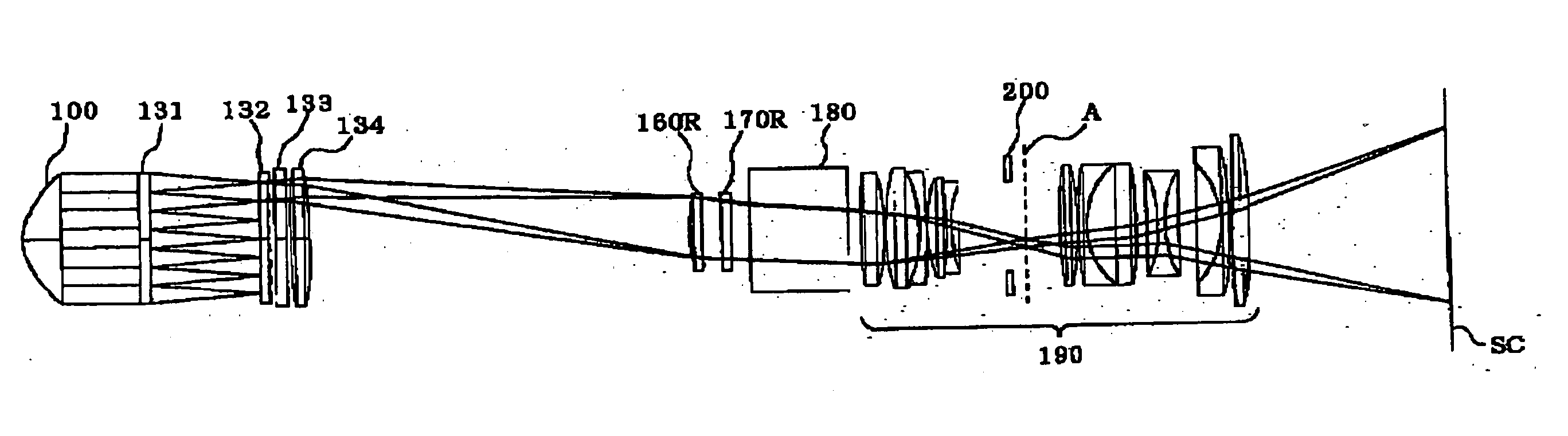
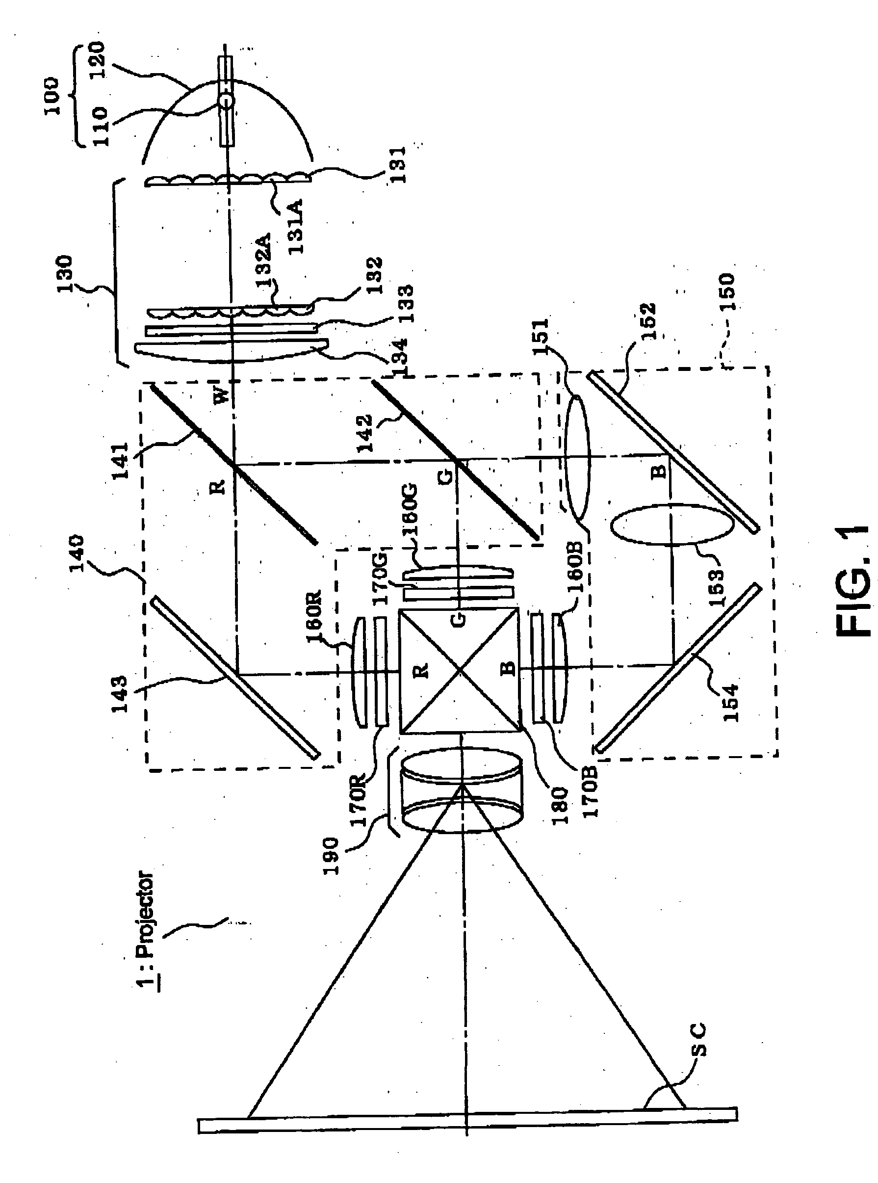
[0029] FIG. 1 shows an optical system of a projector according to an exemplary embodiment of this invention.

[0030] A projector 1 includes a light source 100, an illumination optical system 130, a color separation optical system 140, a relay optical system 150, three condenser lenses 160R, 160G, and 160B (collectively called a condenser lens 160 where describing matters common to the three), liquid crystal panels 170R, 170G, and 170B (collectively called a liquid crystal panel 170 where describing matters common to the three), a cross-dichroic prism 180, and a projection lens 190. The illumination optical system 130 equalizes the illuminance distribution of light emerged from the light source 100 and evenly illuminates a liquid crystal panel. The color separation optical system 140 separates a light beam "W" emitted from the illumination optical system 130 into a red light beam "R", a green light beam "G", and a blue light beam "B", and leads the red light beam "R" and the green ligh...


PUM


Abstract

A projector is provided to ensure the enhancement of contrasts while reducing the needs for alignment accuracy. The projector includes a light source, a first lens array, second lens array, a superimposing lens, and a projection lens lens. The first lens array splits light emitted by the light source into a plurality of partial light beams with a plurality of small lenses that are arranged in a matrix. The second lens array includes a plurality of small lenses corresponding to the plurality of small lenses of the first lens array. The superimposing lens superimposes a plurality of partial light beams emitted by the first lens array and the second lens array on a liquid crystal panel. The projection lens projects light modulated by the liquid crystal panel. In the projector, a diaphragm having an opening that is shaped to be nearly similar to the outline of the second lens array is provided in the vicinity of an area conjugated with the second lens array.

Description

[0001] 1. Field of Invention[0002] The present invention relates to a projector.[0003] 2. Description of Related Art[0004] Projectors have been developed with an aim to enhance their contrasts. Some projectors are provided with a diaphragm in a projection lens. For example, a related art projector is disclosed in Japanese Unexamined Patent Application Publication No. 5-303085. According to the document, a projection display device includes a lighting apparatus, a device to incorporate image data into light beams from the lighting apparatus by modulating the light beams, and a projection optical system that projects the modulated light beams on a screen. The lighting apparatus focuses light emerged from a light source lamp with a focusing device, forms at least one secondary light source, and illuminates the device to incorporate image data with light beams emitted from the secondary light source. The device to incorporate image data is a light bulb using a liquid crystal composite e...

Claims


Application Information

Patent Timeline
IPC IPC(8): G02F1/13G02B3/00G02B5/00G02F1/13357G03B21/00
CPCG02B3/0056G02B5/005G02B27/0927G02B27/0961G03B21/00G03B21/005
Inventor NISHIDA, KAZUHIROUEHARA, KATSUYUKI
Owner SEIKO EPSON CORP
Why Eureka
Try Eureka