Enhanced multimode fiber

a multi-mode fiber and fiber technology, applied in the field of optical fiber communications, can solve the problem that the new core-core interface is not sufficiently spaced from the core-cladding interface, and achieve the effect of widening the operating bandwidth and large coarse wavelength division multiplexed channel sets

Active Publication Date: 2004-10-14
FURAKAWA ELECTRIC NORTH AMERICA INC
View PDF7 Cites 21 Cited by
  • Summary
  • Abstract
  • Description
  • Claims
  • Application Information

AI Technical Summary

Benefits of technology

0023] The invention finally realizes the bit-rate advantage expected of perturbation-induced mode-mixing in a real fiber and, in so doing, enables wider ...

Problems solved by technology

At the same time, the new core-core interface is not sufficiently spaced from the core-cladding int...

Method used


Image

  • Enhanced multimode fiber
  • Enhanced multimode fiber
  • Enhanced multimode fiber

Examples


example 1

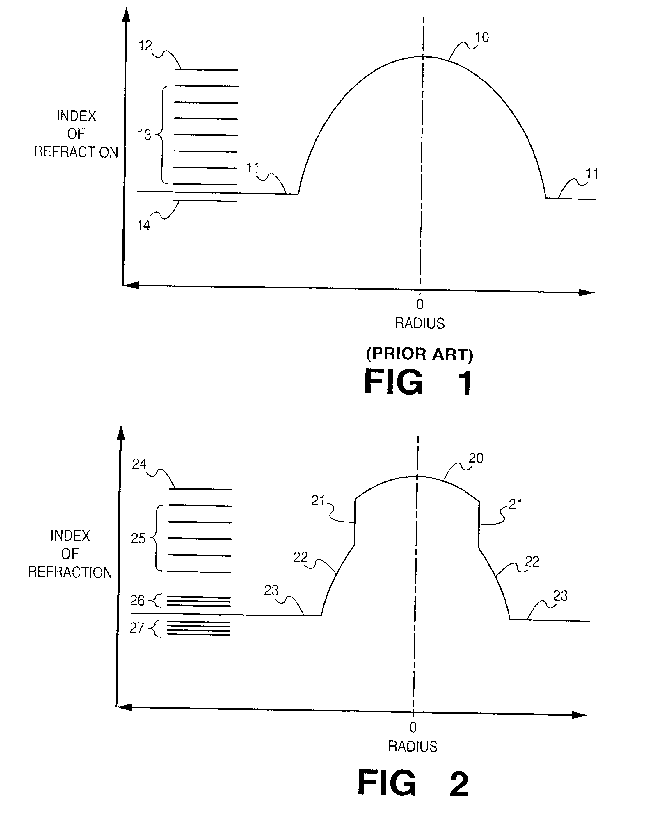
[0139] A conventional, Design 1 fiber, of the profile form shown in FIG. 1, has a .DELTA. of 2% and a core radius of 31.25 .mu.m. At the period of maximum loss, which occurs at A=1000 .mu.m, the loss for 6 pounds load is 12.4 dB. Loss is less than 0.4 dB with a 50 .mu.m increase or decrease in the period. Measured maximum loss period correlates well with the value of 990 .mu.m predicted by Eq. 5.

example 2

[0140] A conventional Design 2 fiber, of the profile of FIG. 1, has a delta of 1% and core radius of 25 .mu.m. At the period of maximum loss, which occurs at .LAMBDA.=1150 .mu.m, the loss for 6 pounds load is 25 dB. Loss is less than 0.4 dB with increase or decrease of 50 .mu.m in the period. This correlates well with the predicted location of the maximum loss at 1110 .mu.m, from Eq. 5. The relative magnitude of the maximum loss ratio of Design 2 to Design 1 is 1.9, which is to be compared with a calculated value of 2.1.

example 3

[0141] A conventional fiber, of the profile form shown in FIG. 1, has a core radius of 30 .mu.m and a .DELTA. value of 1.2%. Location and value of the maximum loss peak, are consistent with Eq. 5 prediction.


PUM


Abstract

A perturbed, multimode optical fiber exhibits order-of-magnitude improved capacity attributed to mode mixing--high per-channel bit rate, and large channel number due to large available bandwidth--without the added loss which, in the past, was associated with the perturbation stream.

Description

FIELD OF THE INVENTION[0001] Optical fiber communications.BACKGROUND OF THE INVENTION[0002] Initial enthusiasm with optical fiber, when first introduced, was soon dampened by a number of considerations. Importantly, early fiber structures--of core size sufficient to support many modes of light--were unexpectedly capacity-limited. It was found that pulse repetition rate in such fiber was limited by pulse spreading, which could obliterate the unoccupied pulse positions that represented the information content of the pulse stream. Laser-generated pulses, single-mode as introduced, were found to have significant higher-mode content as received, with differing modal group velocities accounting for the observed pulse spreading. Intense effort was unsuccessful in avoiding fiber imperfections--e.g., the scattering centers--which had been identified as a primary cause responsible for mode conversion and, accordingly, for generation of the higher-order modes.[0003] A promising remedy was sugg...

Claims


Application Information

Patent Timeline
IPC IPC(8): G02B6/028G02B6/036
CPCG02B6/0288G02B6/03694G02B6/03644
Inventor WHITE, IAN A.
Owner FURAKAWA ELECTRIC NORTH AMERICA INC
Why Eureka
Try Eureka