Method of allocating radio resources in telecommunication system, and telecommunication system

Inactive Publication Date: 2004-10-14
NOKIA CORP
View PDF37 Cites 47 Cited by
  • Summary
  • Abstract
  • Description
  • Claims
  • Application Information

AI Technical Summary

Benefits of technology

0008] The method and system of the invention provide several advantages. In a preferred embodiment of the invention, different beam struc

Problems solved by technology

However, the correspondence between the downlink and uplink beam patterns causes inflexibility when optimi

Method used


Image

  • Method of allocating radio resources in telecommunication system, and telecommunication system
  • Method of allocating radio resources in telecommunication system, and telecommunication system
  • Method of allocating radio resources in telecommunication system, and telecommunication system

Examples


Embodiment Construction

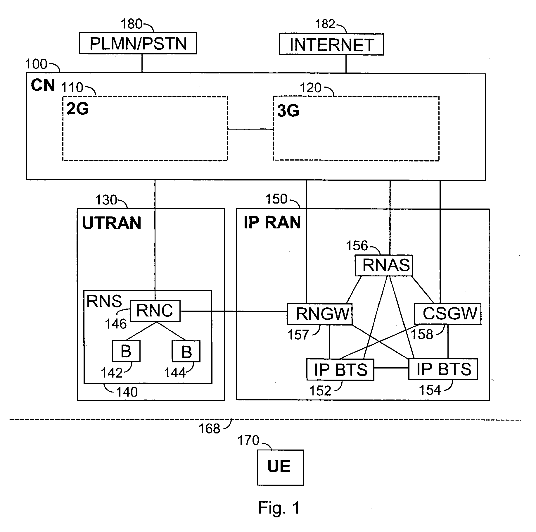
[0020] FIG. 1 is a simplified block diagram illustrating the of telecommunication systems on a network element level.

[0021] The telecommunication system may include a core network (CN) 100, a radio access network (RAN) 130 and user equipment (UE) 170. A radio access network called UTRAN (UMTS Terrestrial Radio Access Network) 130 belongs to the third generation and is implemented by wideband code division multiple access (WCDMA) technology. FIG. 1 also shows an Internet Protocol Radio Access Network 150 (IP RAN) implemented with WCDMA technology. The invention is not, however, restricted to these radio systems, but can be applied to any radio system that uses beam forming techniques in the radio interface.

[0022] The core network 100 may include second generation network elements 110 and third generation network elements 120 connected to the UTRAN 130 and to the Internet Protocol radio access network (IPRAN) 150. The core network 100 may be connected to external networks, such as a P...


PUM


Abstract

The invention relates to a method of allocating radio resources and a telecommunication system including a base station and user equipment. The base station includes a beam forming device configured to form at least two primary beams for signal reception. The antenna array and the beam forming device of the base station are configured to receive a signal transmitted by the user equipment using at least two primary beams, thus providing primary beam-specific signals as output. The base station includes a processing device for determining at least two secondary beam-specific variables associated with two secondary beams using the primary beam-specific signals as input and a transformation between the primary antenna beams and the secondary antenna beams. The telecommunication system further includes an allocation device for allocating radio resources to the user equipment based on the secondary beam-specific variables.

Description

FIELD[0001] The invention relates to a method of allocating radio resources in a telecommunication system, and a telecommunication system.[0002] As wireless data transmission will become more common in the future and the number of users will grow, it is essentially important to increase the capacity of systems by improving their performance. A way of enhancing the performance of a radio system is to allocate radio resources using beam forming in the transmission and reception of a base station. Beam forming is typically implemented using antenna arrangements consisting of one or more antenna elements used both in transmission and reception, and by weighting the signals of the antenna elements. The beam patterns resulting from beam forming typically comprise two or more antenna beams, which can further be associated with beam-specific coding. In an ideal case, each beam thus enables a separate physical radio channel, which reduces the multi-user interference that impairs the performa...

Claims


Application Information

Patent Timeline
IPC IPC(8): H04W16/28
CPCH04W16/28H04W28/18H04W72/04H04W88/08
Inventor YLITALO, JUHA
Owner NOKIA CORP
Why Eureka
Try Eureka