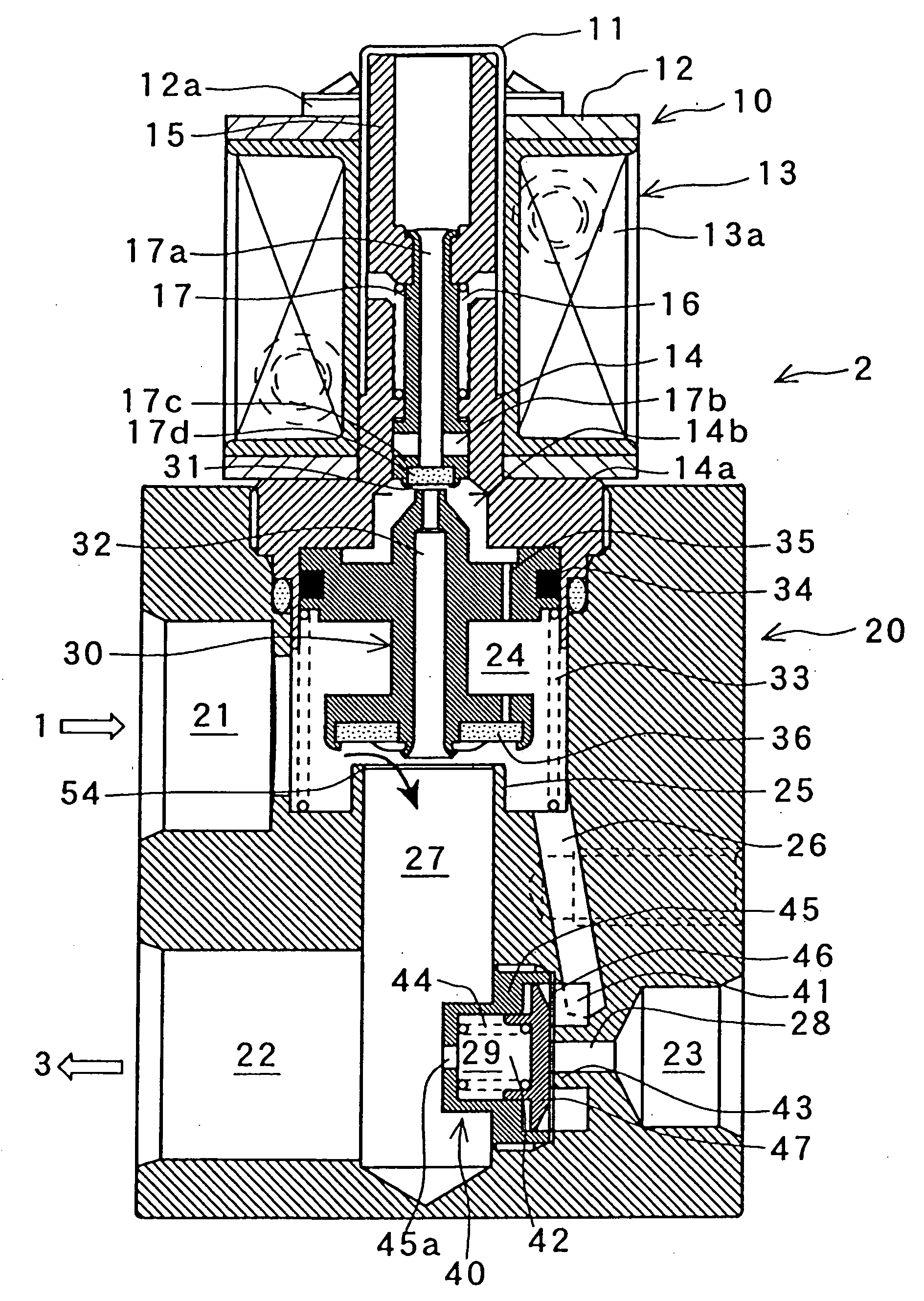
Composite valve
a composite valve and valve body technology, applied in the field of composite valves, can solve the problems of affecting the operation of valves, and affecting the operation of valves, and achieve the effects of reducing cost, reducing parts cost and power consumption, and simplifying the construction of composite valves
- Summary
- Abstract
- Description
- Claims
- Application Information
AI Technical Summary
Benefits of technology
Problems solved by technology
Method used
Image
Examples
first embodiment
[0038] [First Embodiment]
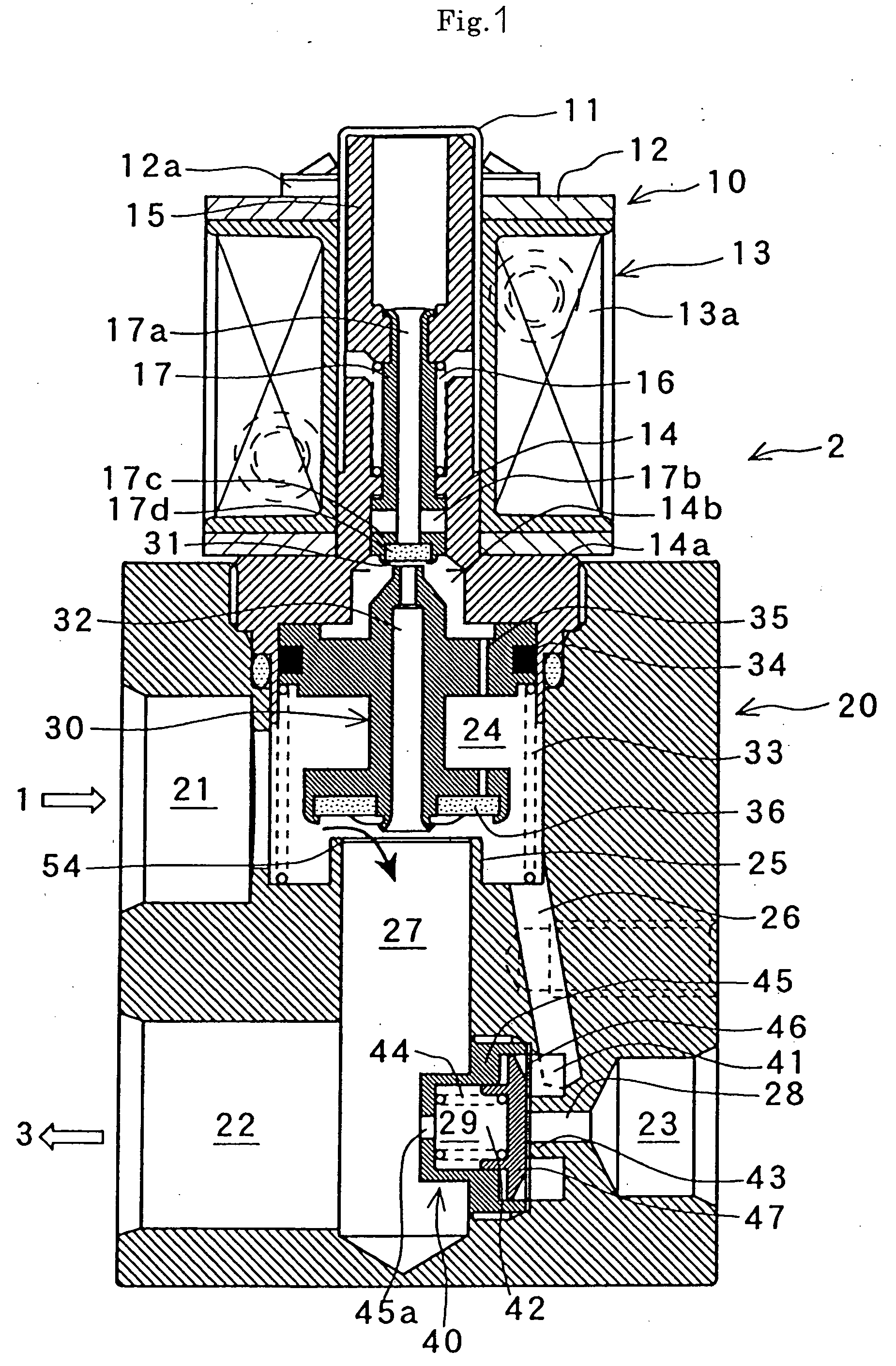
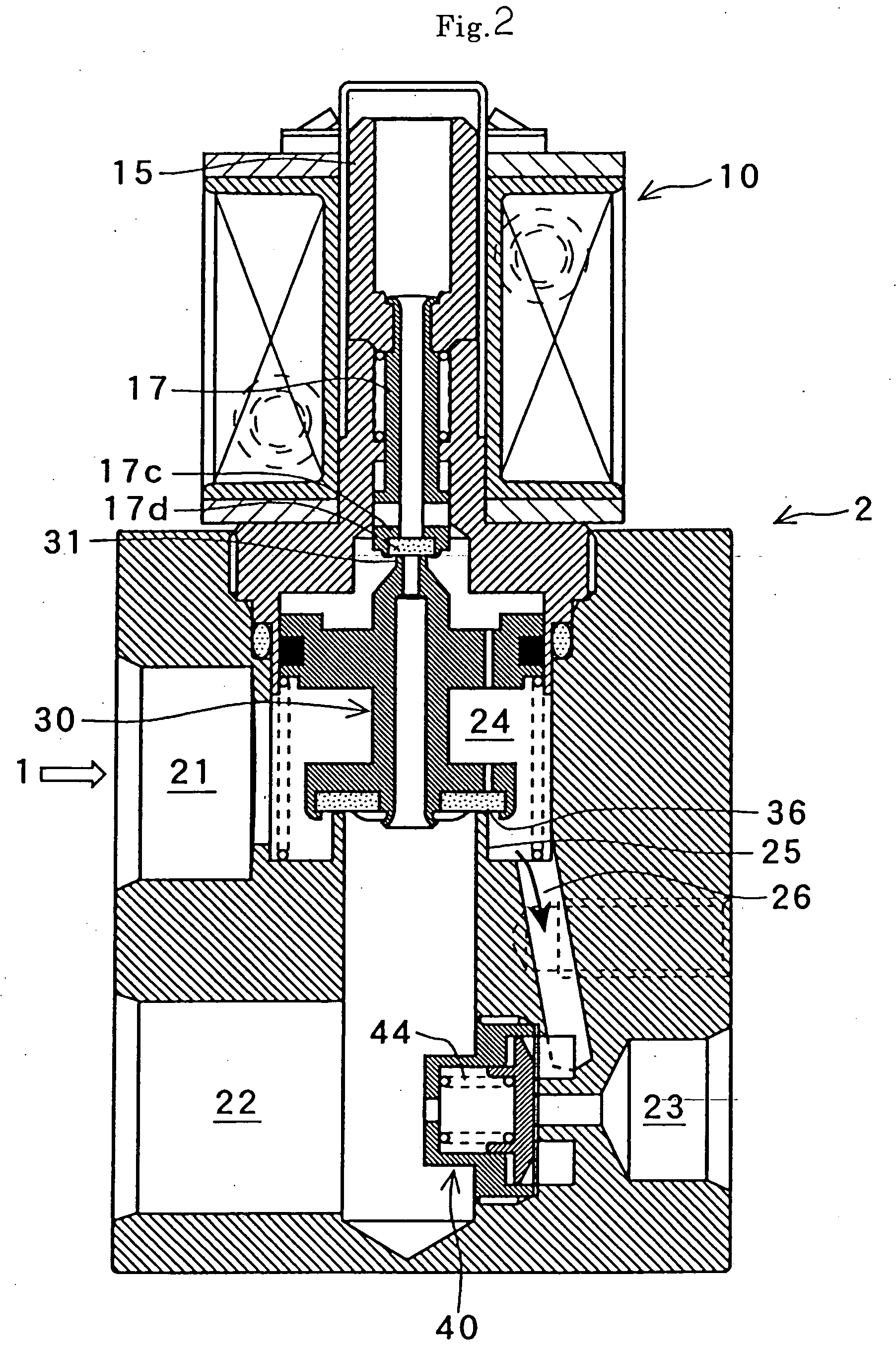
[0039] A first embodiment will first be described with reference to FIGS. 1 to 4 and FIG. 10.
[0040] A composite valve 2 of the invention is applied to a refrigerating cycle that is provided with a hot-gas defrosting cycle, such as the one shown in FIG. 10. This refrigerating cycle is a conventional one, in which a compressor 1, the composite valve 2, a condenser 3, a liquid receiver 4, a check valve 5, an evaporator 6, and an accumulator 7 are coupled to one another by means of piping 8. FIGS. 1 to 3 show the composite valve used in this cycle. Further, the composite valve 2 and the piping 8 at the inlet of the evaporator 6 are coupled like a bypass by means of a bypass pipe 9.
[0041] As shown in FIG. 1, the composite valve 2 comprises a valve body 20, a solenoid valve portion 10, and a differential pressure valve portion 40. The valve portions 10 and 40 are attached to the body 20. In the solenoid valve portion 10, open-close control of a refrigerating cycle...
second embodiment
[0071] [Second Embodiment]
[0072] A second embodiment of the invention will now be described with reference to FIGS. 5 to 9 and FIG. 11. In the description of the second embodiment to follow, the same components of the second embodiment as those of the first embodiment are denoted the same reference numerals in FIGS. 5 to 9 and FIG. 11 as those used in FIGS. 1 to 4 and FIG. 10, and description of those components is omitted here.
[0073] A composite valve 2' according to the second embodiment, which is based on the general configuration of the first embodiment, is characterized in that a check valve portion 50 is attached to a valve body 20. Its solenoid valve portion 10 and differential pressure valve portion 40 are constructed in the same manner as the ones according to the first embodiment. The valve portions 10 and 40 act without regard to the attachment of the check valve portion 50.
[0074] As shown in FIG. 5, the check valve portion 50 is formed adjacent to the solenoid valve port...
third embodiment
[0083] [Third Embodiment]
[0084] A third embodiment of the invention will now be described with reference to FIGS. 12 to 16.
[0085] In the description of the third embodiment to follow, the same components of the third embodiment as those of the first embodiment are denoted the same reference numerals in FIGS. 12 to 16 as those used in FIGS. 1 to 4 and FIG. 10, and description of those components is omitted here.
[0086] In the composite valve 2 of the first embodiment, the diaphragm 46 sometimes may bend (to form a flexure 46'a) and be deformed on the side of the communication hole 28 by a force of differential pressure from the closed differential pressure valve element 47, as shown in FIG. 16.
[0087] According to the third embodiment, deformation of a diaphragm 46' is prevented in a manner such that a stopper 70 is located in a communication hole 28' to restrain deflection of a deformed diaphragm 46'.
[0088] In the third embodiment, as shown in FIG. 12 or 13, a solenoid valve portion 1...
PUM
 Abstract
Description
Claims
Application Information
 - R&D
- Intellectual Property
- Life Sciences
- Materials
- Tech Scout
- Unparalleled Data Quality
- Higher Quality Content
- 60% Fewer Hallucinations
Browse by: Latest US Patents, China's latest patents, Technical Efficacy Thesaurus, Application Domain, Technology Topic, Popular Technical Reports.
© 2025 PatSnap. All rights reserved.Legal|Privacy policy|Modern Slavery Act Transparency Statement|Sitemap|About US| Contact US: help@patsnap.com


