
Gel mixing system

Inactive Publication Date: 2004-11-04
ALLEN THOMAS E
View PDF16 Cites 52 Cited by
  • Summary
  • Abstract
  • Description
  • Claims
  • Application Information

AI Technical Summary

Benefits of technology

[0011] Still a further object of the invention is to provide a system that does not require special chemicals to accelerate the hydration process. By not requiring special chemicals, some of which are considered harmful to the environment, the end gel product is more economical and more environmentally friendly.
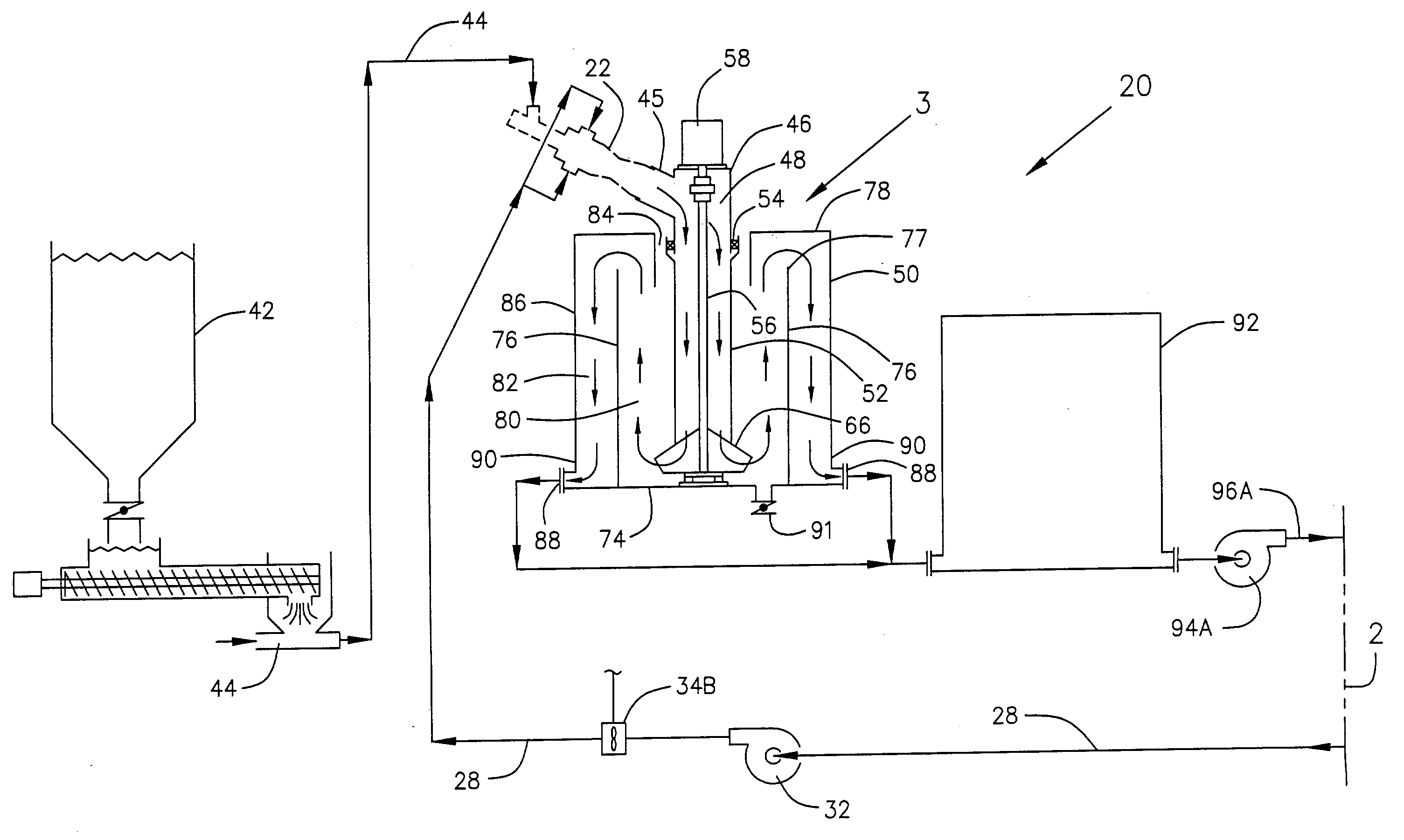
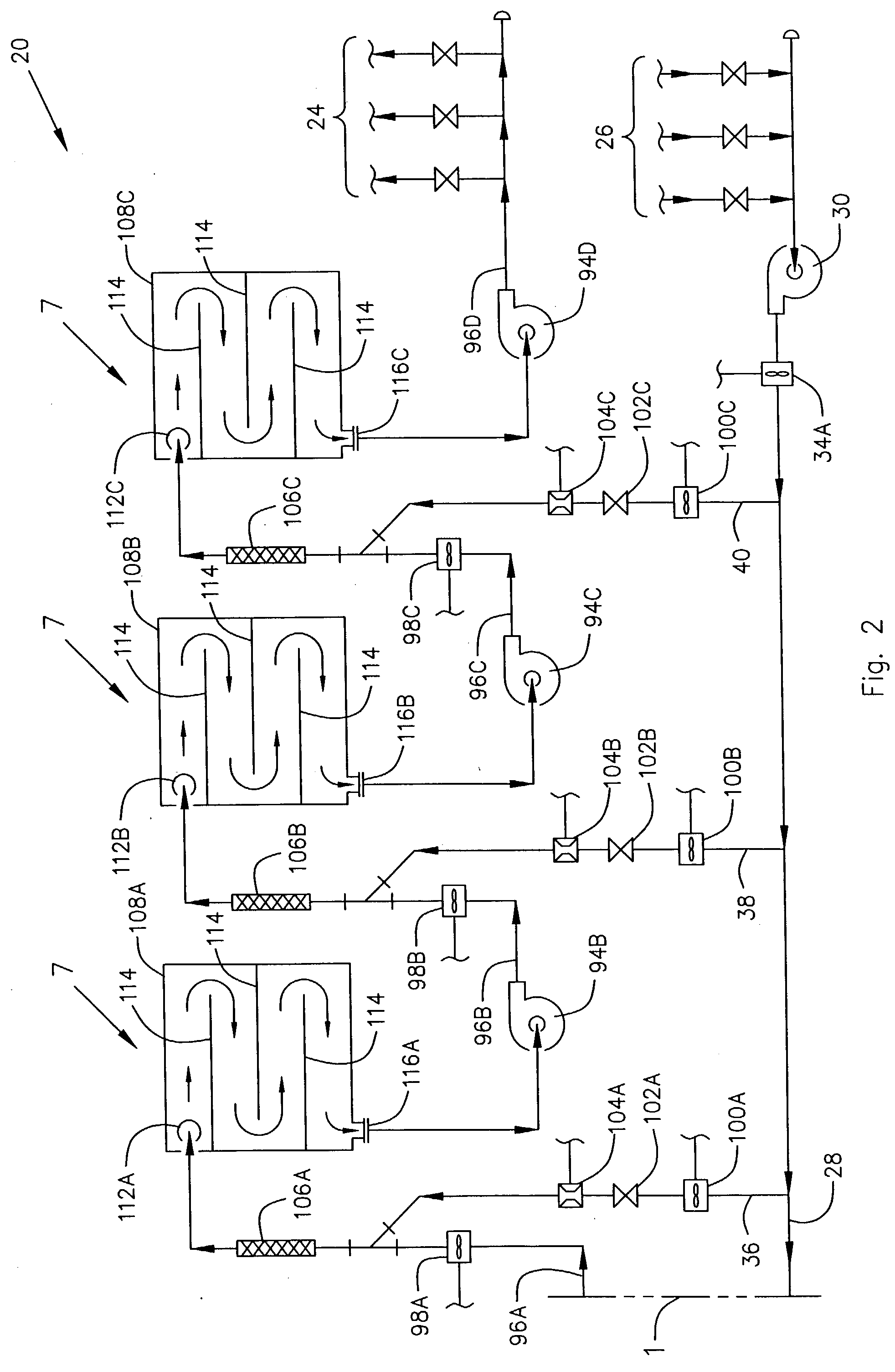
[0013] The present invention is a gel mixing system that employs a dynamic diffuser for quickly removing the air from the fluid as the fluid exits a traditional gel mixer and employs progressive dilution of a concentrate fluid as it hydrates into a gel in a series of hydration tanks to maximize hydration time without allowing the gel to become so viscous that it is not easily pumped. High shear agitation of the fluid between the hydration tanks helps to increase the hydration rate. Progressive dilution of a concentrate gel in the hydration tanks increases residence time of the gel in the tanks and results in longer hydration time in the limited tank space available. As a result, the present system is able to continuously produce gel that is almost fully hydrated by the time it is transferred to the fracturing blender without the need for an increase in the volume of the hydration tanks.

Problems solved by technology

Because the equipment is truck or trailer mounted, the tank volume available for allowing the gel to hydrate after it is mixed with water is limited.
One of the problems with current gel mixing systems is that, without the use of large hydration tanks, the gel is not fully hydrated to the desired viscosity before the gel is transferred to the fracturing blender.
Large hydration tanks can not be readily skid, truck or trailer mounted for use at a well site.
Without using large hydration tanks, the gel will have a short residence time of the liquid within the smaller skid, truck or trailer mounted hydration tanks which does not allow sufficient time for the gel to become adequately hydrated before it is transferred to the fracturing blender prior to being used in the well.
The high sheer pumps used in the present system tend to disrupt or sheer this gelatinous outer coating off of the micelles.
Progressive dilution of a concentrate gel in the hydration tanks increases residence time of the gel in the tanks and results in longer hydration time in the limited tank space available.

Method used


Image

  • Gel mixing system
  • Gel mixing system
  • Gel mixing system

Examples


Embodiment Construction

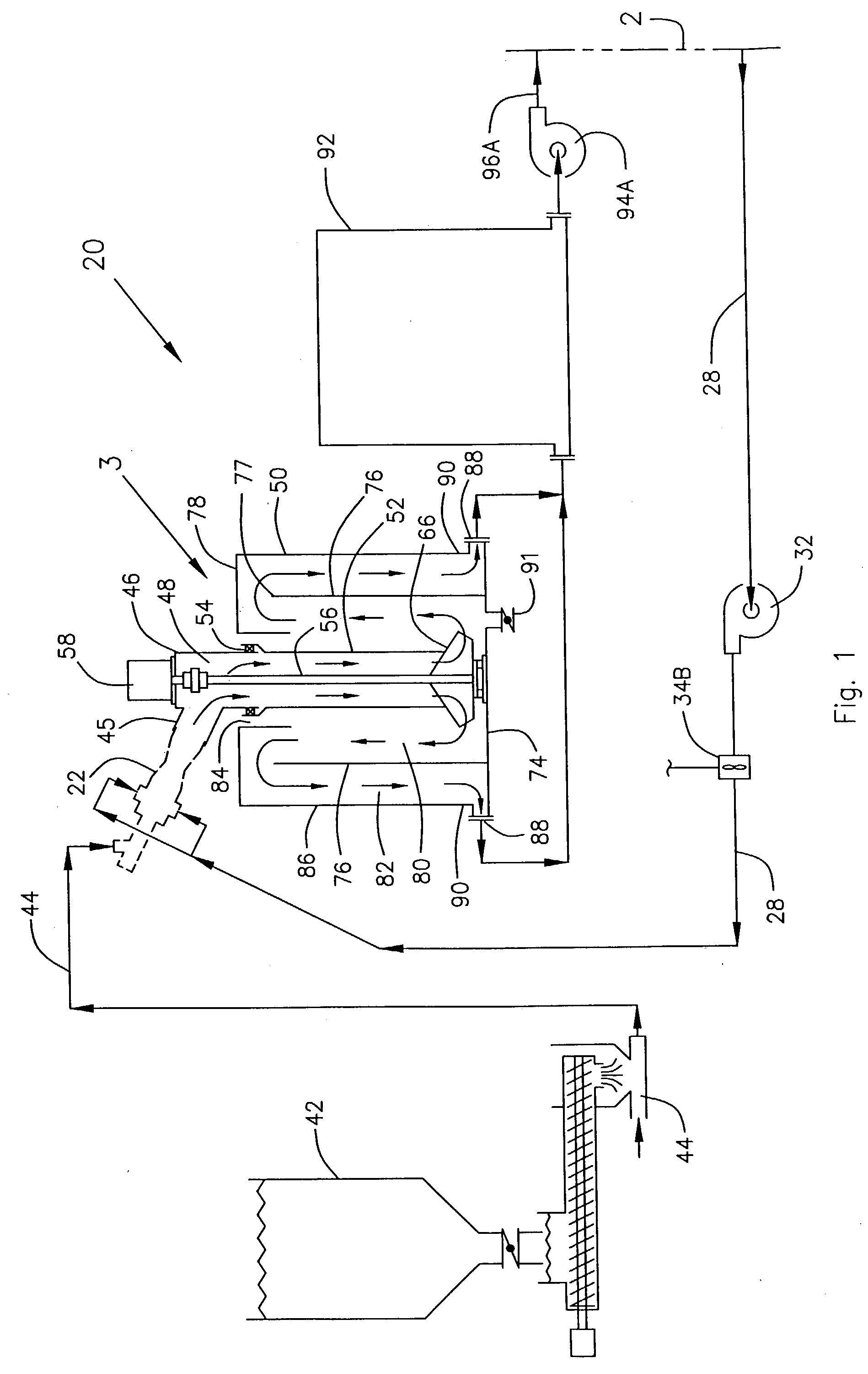
[0026] Referring now to the drawings and initially to FIGS. 1 and 2, there is shown a diagram of a gel mixing system 20 constructed in accordance with a preferred embodiment of the present invention. Upstream of the system 20, a gel mixer 22 such as the type taught by U.S. Pat. No. 5,382,411, issued on Jan. 17, 1995 to the present inventor, supplies liquid gel mixture to the system 20. Downstream of the system 20, the system 20 supplies hydrated gel to a gel discharge manifold 24 which in turn supplies the hydrated gel to a fracturing blender where sand or other proppant and chemicals are blended with the hydrated gel before the mixture is pumped to a well bore. The fracturing blender is not illustrated in the drawings.

[0027] As illustrated in FIGS. 1 and 2, a suction manifold 26 supplies dilution water to the gel mixer 22 via mixer dilution water line 28 and water pumps 30 and 32. Mix water flow meters 34A and 34B are provided in mixer dilution water line 28. Mix water flow meter 3...


PUM

PropertyMeasurementUnit
Timeaaaaaaaaaa
Flow rateaaaaaaaaaa
Concentrationaaaaaaaaaa

Abstract

A gel mixing system that employs a dynamic diffuser for quickly removing the air from the fluid as the fluid exits a traditional gel mixer and employs progressive dilution of the gel in a series of hydration tanks to maximize hydration time without allowing the gel to become so viscous that it is not easily diluted or pumped. High shear agitation of the fluid between the hydration tanks helps to increase the hydration rate. Progressive dilution of the gel increases residence time of the gel in the tanks and results in longer hydration time in the limited tank space available, resulting in continuous production of gel that is almost fully hydrated when it is pumped to the fracturing blender and subsequently to the well bore without the need for an increase in the volume of the hydration tanks.

Description

[0001] 1. Field of the Invention[0002] The present invention relates to a system for continuously mixing gel fluid that will be used to transport fracturing proppant into a well formation to prop open the formation after fracturing. The system employs a dynamic diffuser to remove air from the fluid as the fluid comes out of a mixer and employs progressive dilution of the fluid after the fluid leaves the dynamic diffuser and travels through a series of hydration tanks. High shear agitation is used to help mix the gel fluid and dilution fluid as it moves through the hydration tanks. This system allows increased hydration time and more complete hydration of the gel fluid in the limited tank space of skid, truck, or trailer mounted portable equipment than is possible with current gel mixing systems.[0003] 2. Description of the Related Art[0004] Currently when mixing guar powder and water to form a liquid gel for use to transport fracturing proppant into a well formation, the mixing is d...

Claims


Application Information

Patent Timeline
IPC IPC(8): B01F3/12B01F5/06B01F5/20B01F7/16B01F13/10
CPCB01F3/1221B01F3/1271B01F5/061B01F5/0646B01F5/0647B01F5/205B01F7/1635B01F13/103B01F23/59B01F23/53B01F25/431B01F25/4331B01F25/433B01F25/721B01F27/8111B01F33/8212
Inventor ALLEN, THOMAS E.
Owner ALLEN THOMAS E
Learn More