Method and apparatus for skew adjustment, data transmission system having skew adjustability

a data transmission system and skew adjustment technology, applied in the field of data transmission systems, can solve problems such as data transmission systems, complex circuits and additional signal lines, data transmission systems, and data transmission systems

Inactive Publication Date: 2004-11-11
AGILENT TECH INC
View PDF1 Cites 33 Cited by
  • Summary
  • Abstract
  • Description
  • Claims
  • Application Information

AI Technical Summary

Problems solved by technology

However, in the instance of the above-described types of data transmission systems, there are cases in which, if the time correlation between the clock and the data is inappropriate, the data transmitted to the receiver will be unstable.
In addition, the data transmission system will further comprise complex circuits and additional signal lines for performing an optimal skew adjustment optimal for a transmission rate (see Japanese Kokai Patent No.
Complex circuits and additional signal lines become factors that interfere with miniaturization, cost reduction, and the like, of data transmission systems.

Method used


Image

  • Method and apparatus for skew adjustment, data transmission system having skew adjustability
  • Method and apparatus for skew adjustment, data transmission system having skew adjustability
  • Method and apparatus for skew adjustment, data transmission system having skew adjustability

Examples


first embodiment

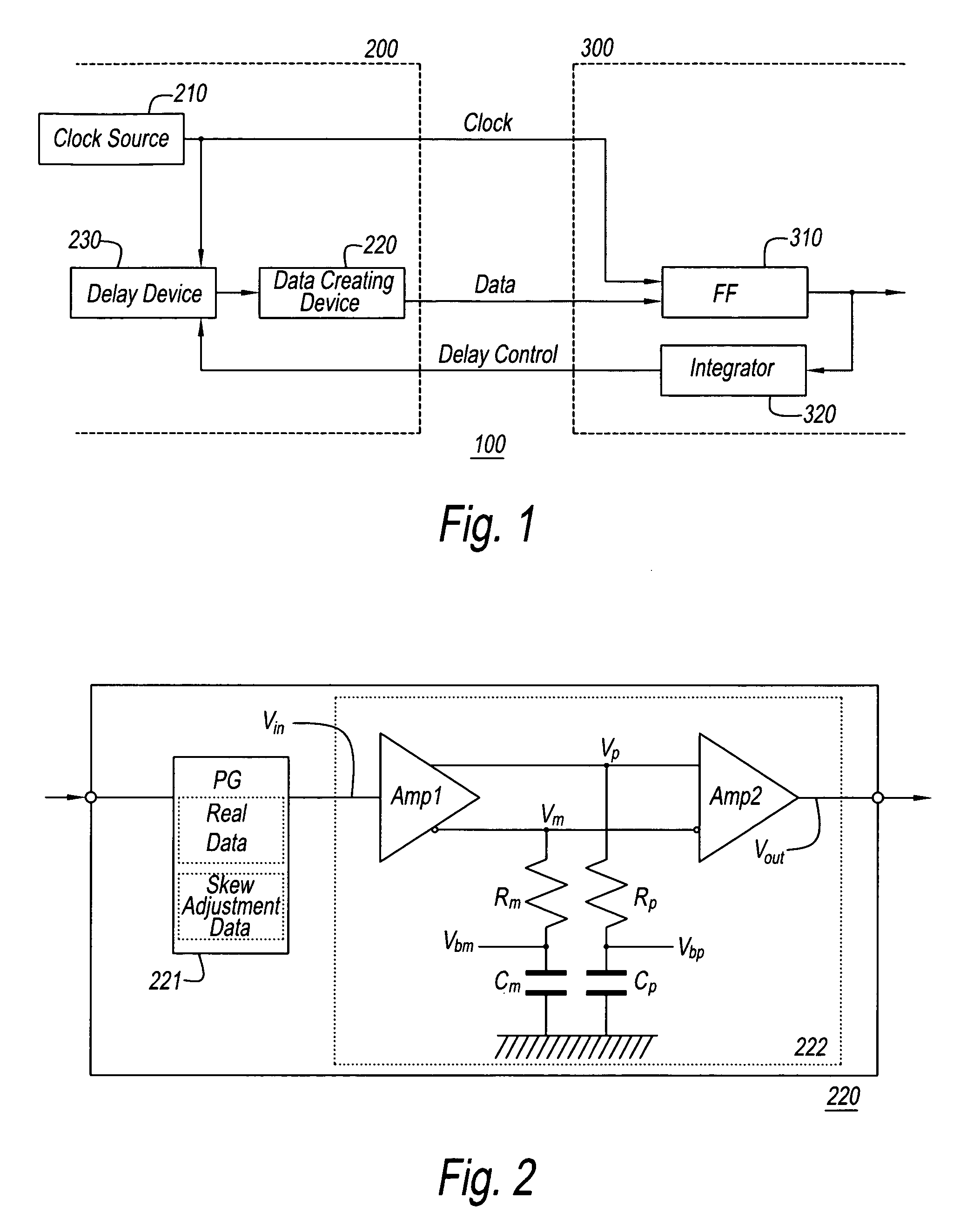
[0035] The present invention will now be described based on preferred embodiments shown in the attached drawings. The first embodiment is a serial data transmission system with which skew adjustment is performed by the method of the present invention. A structural diagram of this system is shown in FIG. 1.

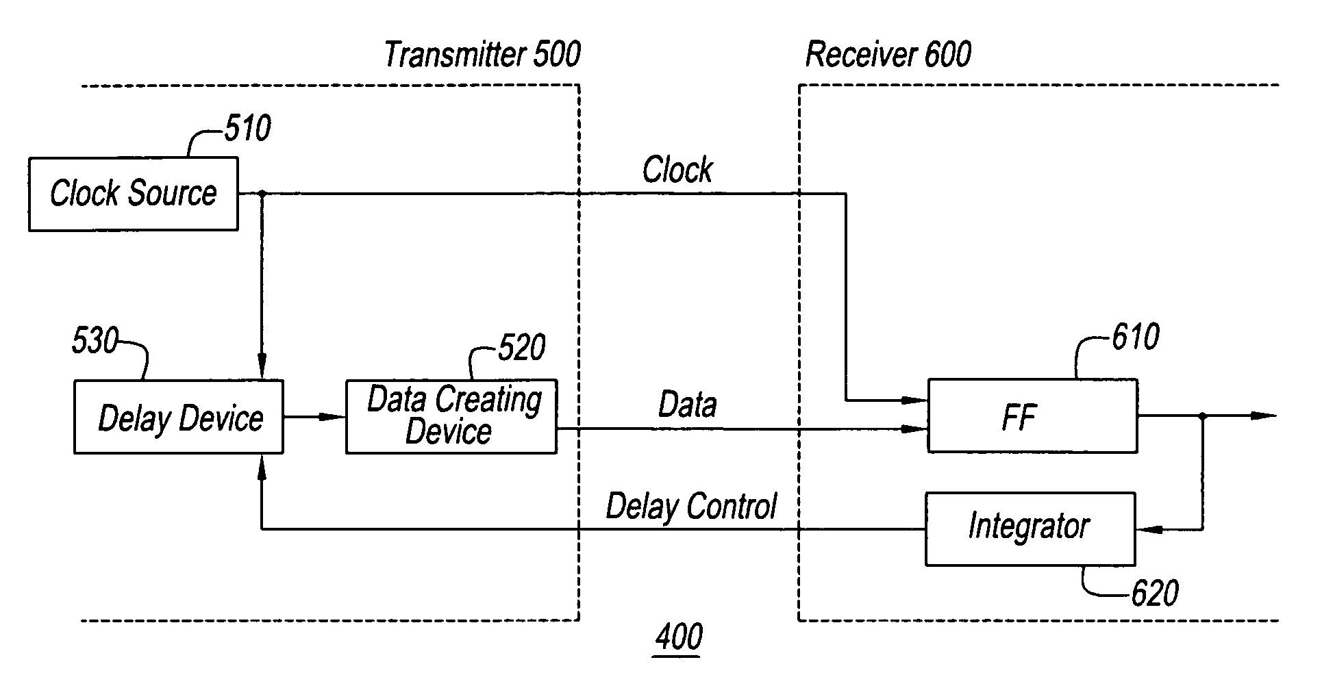
[0036] A serial data transmission system 100 in FIG. 1 comprises a transmitter 200 and a receiver 300.

[0037] Transmitter 200 comprises a clock generator 210, a data generator 220, and a delay device 230. Clock generator 210 is a device that supplies the clock signals to transmitter 200 and the clock signals are transmitted to outside the device. By means of the present embodiment, the clock signals that are supplied by clock generator 210 are rectangular wave signals. Delay device 230 is a device that applies a specific time delay to the inputted signals. It receives the clock signals from clock generator 210, applies time delay to the clock signals, and outputs the delayed signals...

second embodiment

[0051] The skew adjustment method of the second embodiment is described in detail below. The output signals of integrator 320 are shown in FIG. 6 for clarification. Top signal line X represents the output signals of integrator 320 at transmission rate RX. Moreover, bottom signal line Y represents the output signals of integrator 320 at transmission rate RY. It should be noted that transmission rate RX is faster than transmission rate RY. Moreover, T0 is the amount of skew still present between the clock signal and the data signal when the amount of time delay applied by delay device 230 is minimized. T0 is not the delay added intentionally but delay which serial data transmission system 100 adds primitively. T0 is understood to be a representative approximate value and is not understood to be an exact value. The part of signal line X and signal line Y whose level changes with this T0 is shown by the broken line in FIG. 6, while the part where the level changes with the time delay ap...

third embodiment

[0055] By the way, the devices and transmission paths through which signals pass each have unique group delay properties. In general, these group delay properties are properties such that the amount of delay varies with frequency. Consequently, when the frequency distribution of the signals that are input changes from moment to moment, the amount of jitter applied to the signals that pass through the devices and transmission paths is generally high. Real data signals are examples of signals whose frequency distribution changes from moment to moment. On the other hand, the amount of jitter applied to the signals that pass through the devices and transmission paths is generally small when the distribution frequency of the signals that are input is constant. Clock signals and similar signals are examples of signals whose frequency distribution is constant. This applies also to pattern generator 221, waveform adjustment device 222, delay device 230, and similar devices. Consequently, it...


PUM


Abstract

A data transmission system with which optimal skew adjustment is achieved by a structure transmitting skew adjustment signals in place of data signals and detecting the amount of skew between the clock signals and the data signals. The skew adjustment signals are alternating signals with twice the period of the clock signals, and one signal state persists for a longer time than the other signal state.

Description

BACKGROUND OF THE INVENTION 1. Field of the Invention[0001] The present invention pertains to a data transmission system and in particular, relates to a data transmission system including skew adjustment at any transmission rate.[0002] 2. Description of the Prior Art[0003] Changes in transmission signal waveform greatly influence the transmission quality of data transmission systems. Reducing fluctuations in data transition timing, that is, jitter reduction, is a particularly important topic associated with data transmission systems.[0004] Methods of reducing the effects of jitter by retiming data using a clock synchronized with the data in the middle or at the end of the transmission path, and similar methods have been used with high-speed data transmission systems in the past. Specifically, the data and the clock signals are transmitted concurrently in a data transmission system and the state of the data is kept in response to the transition of the clock using a flip-flop or simil...

Claims


Application Information

Patent Timeline
Patent Type & Authority Applications(United States)
IPC IPC(8): G06F1/10G06F1/12H04L7/00H04L7/033H04L25/14
CPCH04L7/00H04L7/0008H04L7/0033H04L7/033H04L25/14H04L7/0091
Inventor YAMASHITA, HIDEKI
Owner AGILENT TECH INC
Why Eureka
Try Eureka