
Methods and devices for capturing and fixing leaflets in valve repair

a leaflet and valve technology, applied in the field of medical methods, devices and systems, can solve the problems of valve leaflet prolapse, valve leaflet regurgitation, regurgitation, etc., and achieve the effect of stable and effective fixation of leaflets

Inactive Publication Date: 2004-11-11
EVALVE
View PDF99 Cites 223 Cited by
  • Summary
  • Abstract
  • Description
  • Claims
  • Application Information

AI Technical Summary

Benefits of technology

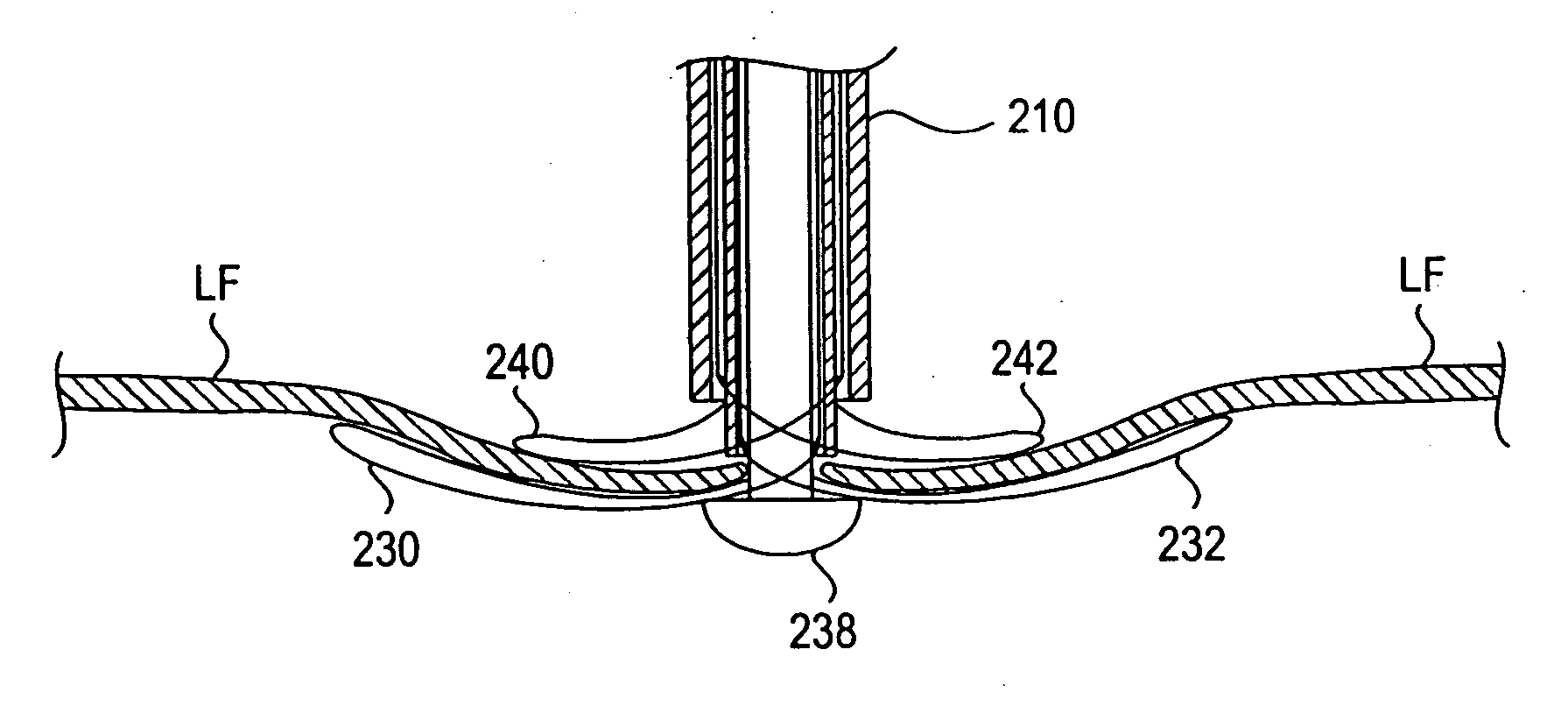
[0083] The interventional tool 100 is dimensioned at its waist 110 to fit between adjacent chordae where the chordae attach to the free edge. The elements 106 may be dimensioned to have a width 112 which is greater than the distance between the adjacent chordae, effectively trapping the chordae, however this is not necessary. In addition, the opposing tensioning force of the chordae on the free edge FE of the leaflets helps secure the leaflets LF on the elements 106. Such dimensioning and positioning prevents displacement of the leaflets LF from the interventional tool 100 due to the diastolic pressure gradient on the leaflets LF and relative movement of the annulus to the elements 106. This is shown in FIG. 5, a short-axis view of the mitral valve MV from the atrial side during diastole wherein the leaflets LF remain in position against the elements 106 surrounded by openings 114 which result from the diastolic pressure gradient. This simulates the double orifice geometry of a standard surgical bow-tie repair. Color Doppler echo will show if the regurgitation of the valve has been reduced. If the resulting mitral flow pattern is satisfactory, the leaflets may be fixed together in this orientation with a suture 115 or fixation device, as shown in FIG. 5A. If the resulting color Doppler image shows insufficient improvement in mitral regurgitation, the interventional tool 100 may be repositioned. This may be repeated until an optimal result is produced wherein the leaflets LF may then be fixed.
[0121] In use, the tool 100 is positioned between the valve leaflets LF, as shown in a top view in FIG. 29, so that the proximal elements 400 are disposed against the atrial surface (in an atrial approach) of the valve. The distal elements 404 are disposed against the ventricular surface of the valve and thus are out of view. Such placement of the proximal elements 400 provides four target points 406 on the valve leaflet LF, two target points 406 per leaflet LF. Advancement of one or more fixation tools through the guide conduits 304 allows placement of sutures and optionally anchors 324 through the leaflets LF at the target points 406 by the fixation tools. Once sutures and optionally anchors 324 are placed through each of the target points 406, the sutures may be pulled together, cinched and fastened in place. FIG. 30 illustrates such action as the target points 406 will be drawn together in the direction of the arrows. This may provide a more sturdy and effective fixation of the leaflets and therefore repair of the valve.

Problems solved by technology

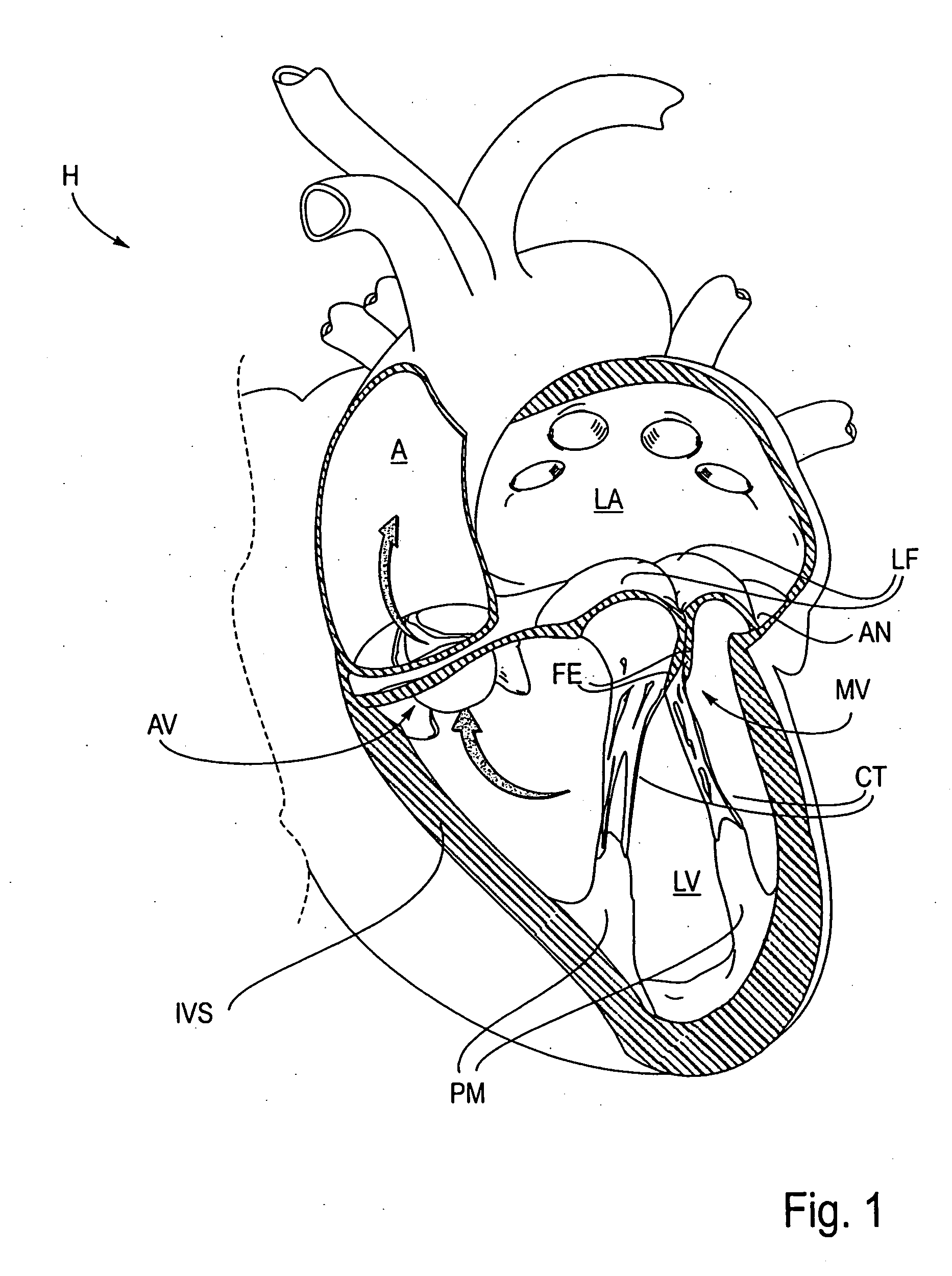
A number of structural defects in the heart can cause mitral valve regurgitation.
Regurgitation occurs when the valve leaflets do not close properly allowing leakage from the ventricle into the atrium.
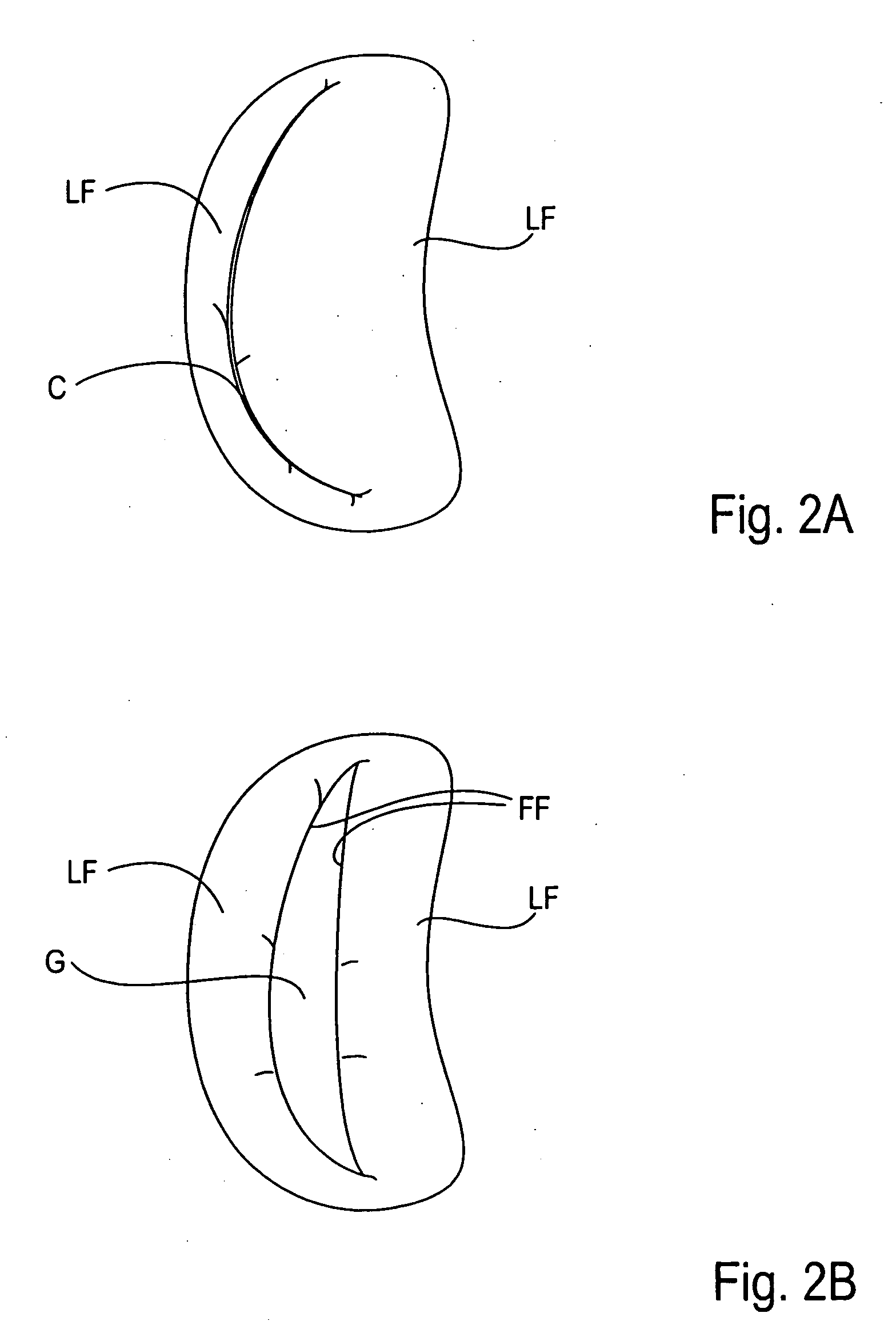
This results in a gap G which allows blood to leak through the valve during ventricular systole.
Ruptured chordae can also cause a valve leaflet to prolapse since inadequate tension is transmitted to the leaflet via the chordae.
While the other leaflet maintains a normal profile, the two valve leaflets do not properly meet and leakage from the left ventricle into the left atrium will occur.

Method used


Image

  • Methods and devices for capturing and fixing leaflets in valve repair
  • Methods and devices for capturing and fixing leaflets in valve repair
  • Methods and devices for capturing and fixing leaflets in valve repair

Examples


first embodiment

[0129] In the first embodiment, referring to FIG. 42, the interventional catheter 500 comprises an elongate shaft 502 having at least one capture device 504 and guide conduit 506 disposed near its distal end 508. The capture device 504 comprises distal loops 510 which are located near the tip 512 of the catheter. Two distal loops 510 are shown, one on each side of the catheter 500, for the capturing of two valve leaflets. The distal loops 510 are retracted for introduction of the catheter 500 through a previously placed guidecatheter. Proximal loops 514 and guide conduits 506 are also shown. Since both the proximal loops 514 and the guide conduits 506 are located proximal to the distal loops and approach the atrial surface of the leaflets, they may be interconnected at the guide conduit cuff 516 as shown. In addition, such interconnectivity may provide advantages which have been presented earlier in relation to embodiments having similar interconnectivity. It may be appreciated, how...

second embodiment

[0136] In the second embodiment, referring to FIG. 52, the interventional catheter 1050 comprises an elongate shaft 1052 and a detachable capture device 1054. The capture device 1054 comprises, among others, proximal elements 1056 and distal elements 1058. Such a capture device 1054 is similar to that presented in FIGS. 17C-17D. Again, the proximal elements 1056 may be separately deployable from the distal elements 1058. As shown, the distal elements 1058 are deployed so that they are extended radially outward from the shaft 1052. The proximal elements 1056 may be held against the shaft by sutures 1060 which are drawn up within the shaft 1052. In this orientation, the catheter 1050 may be manipulated between the leaflets so that the distal elements 1058 are positioned against the ventricular surface of the valve leaflets LF.

[0137] Referring to FIG. 53, the proximal elements 1056 may then be released by slacking the sutures 1060. This allows the preformed elements 1056 to extend radi...


PUM


Abstract

The present invention provides methods and devices for grasping, and optional repositioning and fixation of the valve leaflets to treat cardiac valve regurgitation, particularly mitral valve regurgitation. Such grasping will typically be atraumatic providing a number of benefits. For example, atraumatic grasping may allow repositioning of the devices relative to the leaflets and repositioning of the leaflets themselves without damage to the leaflets. However, in some cases it may be necessary or desired to include grasping which pierces or otherwise permanently affects the leaflets. In some of these cases, the grasping step includes fixation.

Description

CROSS-REFERENCES TO RELATED APPLICATIONS[0001] This application is a continuation of U.S. patent application Ser. No. 09 / 894,463 (Attorney Docket No. 020489-000400US), filed Jun. 27, 2001, which was a continuation-in-part of, and claims the benefit of priority from, co-pending U.S. patent application Ser. No. 09 / 544,930 (Attorney Docket No. 20489-000110US), filed Apr. 7, 2000 (now U.S. Pat. No. 6,629,534), which is claims the benefit of prior Provisional Application No. 60 / 128,690 (Attorney Docket No. 019196-000600US), filed on Apr. 9, 1999 under 37 CFR .sctn.1.78(a), the full disclosures of which are hereby incorporated herein by reference.[0002] 1. Field of the Invention[0003] The present invention relates generally to medical methods, devices, and systems. In particular, the present invention relates to methods, devices, and systems for the endovascular or minimally invasive surgical repair of the valves of the heart, particularly the mitral valve.[0004] Mitral valve regurgitatio...

Claims


Application Information

Patent Timeline
IPC IPC(8): A61B17/00A61B17/04A61B17/06A61B17/064A61B17/068A61B17/12A61B17/122A61B17/128A61F2/24A61L27/00A61L29/00
CPCA61B8/10A61B2017/00986A61B17/04A61B17/0401A61B17/0469A61B17/0482A61B17/0487A61B17/0625A61B17/064A61B17/0643A61B17/0644A61B17/068A61B17/07207A61B17/08A61B17/122A61B17/1227A61B17/1285A61B17/29A61B18/1492A61B18/18A61B18/20A61B19/026A61B2017/00243A61B2017/00575A61B2017/00579A61B2017/00588A61B2017/00592A61B2017/00606A61B2017/00623A61B2017/00783A61B2017/00867A61B2017/0404A61B2017/0409A61B2017/0417A61B2017/0419A61B2017/0443A61B2017/0458A61B2017/0464A61B2017/047A61B2017/0472A61B2017/0474A61B2017/0488A61B2017/0496A61B2017/06052A61B2017/06057A61B2017/06076A61B2017/061A61B2017/06171A61B2017/0641A61B2017/088A61B2017/2908A61B2017/2926A61F2/2442A61B17/00234A61B50/30A61F2/246A61F2/2463A61B17/12
Inventor GOLDFARB, ERIC A.DELL, KENT D.FAN, SYLVIA WEN-CHINMARTIN, BRIAN B.POWELL, FEROLYN T.RASCHDORF, ALFRED H.THORNTON, TROY L.
Owner EVALVE
Learn More