Soft tissue securing anchor

Inactive Publication Date: 2004-11-18
VITE TECH
View PDF12 Cites 29 Cited by
  • Summary
  • Abstract
  • Description
  • Claims
  • Application Information

AI Technical Summary

Problems solved by technology

The conventional devices have some disadvantages which render them less than optimal for use in many operative procedures.
Once a conventional anchor is secured in place, a surgeon is generally not able to rethread a suture through the suture-securing hole if the suture should break or otherwise come louse.
This leads to the inefficient use of t

Method used


Image

  • Soft tissue securing anchor
  • Soft tissue securing anchor
  • Soft tissue securing anchor

Examples


Embodiment Construction

)

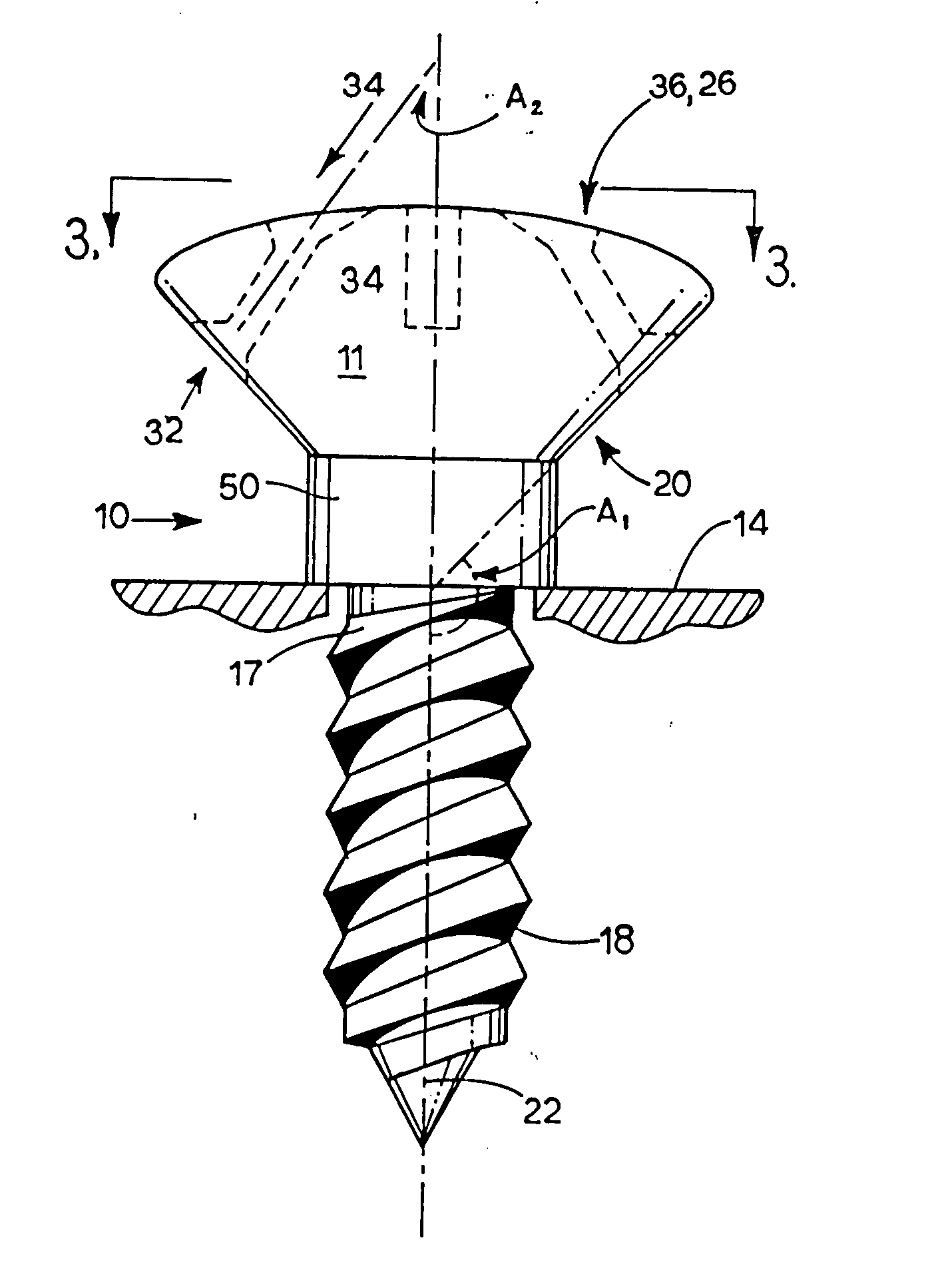
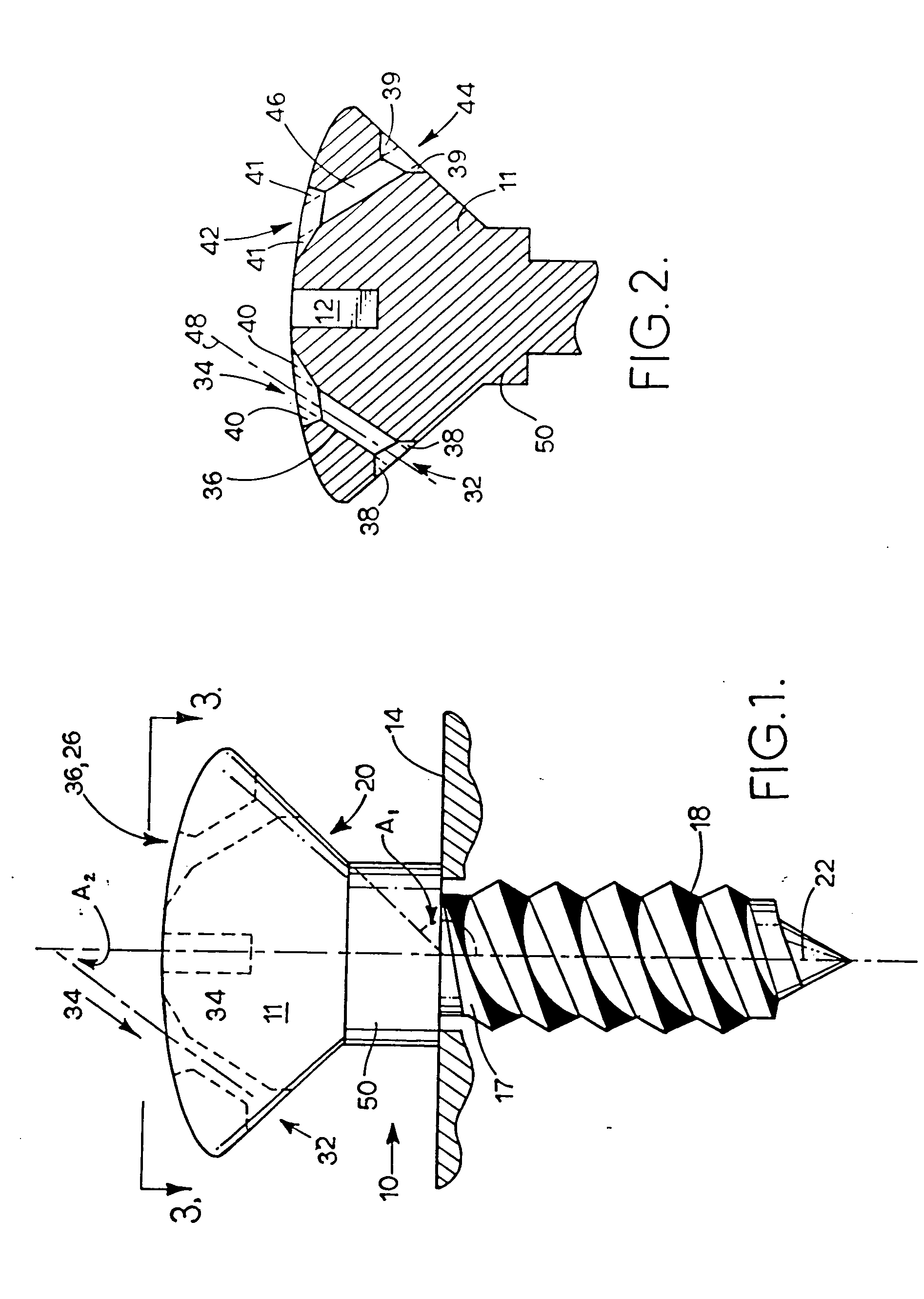
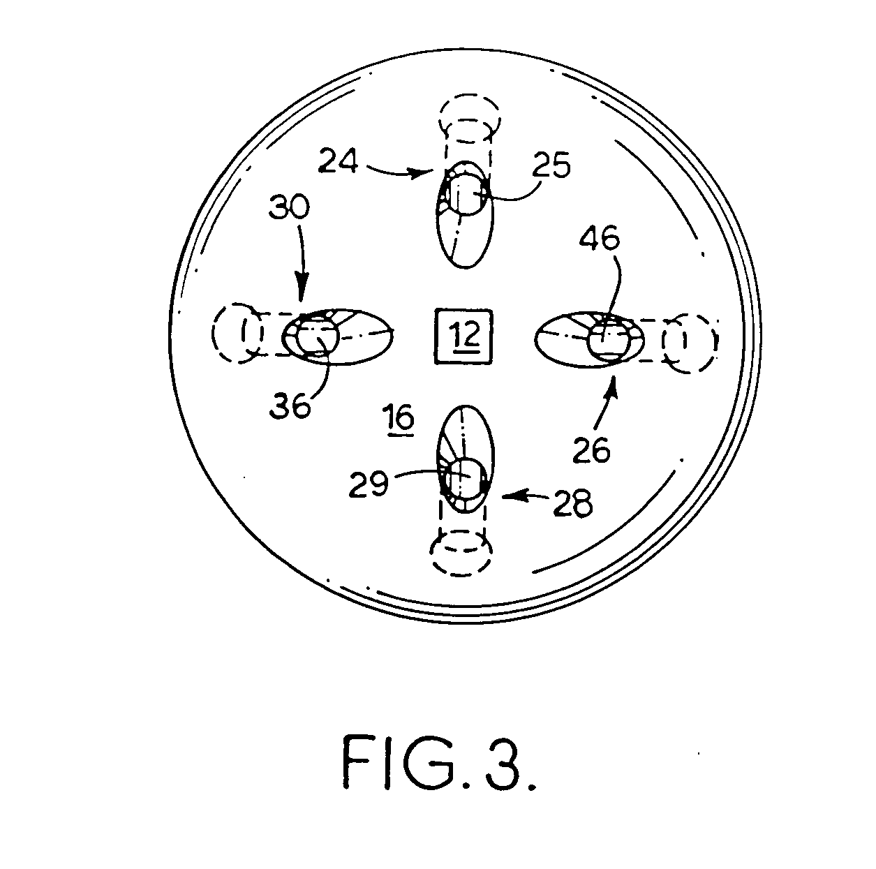
[0026] Referring to FIG. 1, soft tissue securing anchor 10 includes head 11 and securing end 18. Securing end 18 may include any conventional means of securing a suture anchor into bone such as threads, barbs, fingers, toggle or molly bolts, and rivets. Suture anchor 10 may be secured into bone by any conventional means such as the application of torque or press-fit. The currently preferred embodiment of the present invention is a threaded, self tapping screw having a shoulder 50 which delineates head 11 from shank 17. Shoulder 50 provides a visual and physical indication to the surgeon to stop inserting soft tissue securing anchor 10 when shoulder 50 contacts bone 14. The size of shoulder 50 and the shape of head 11 are selected to permit access by surgical needle to both upper and lower apertures such as upper aperture 34 and lower aperture 32. Raising lower aperture 32 above bone 14 permits easy access to lower aperture 32. Head 11 may include a means for accommodating a drive t...


PUM


Abstract

A surgical anchor is provided with one or more anchor holes distributed around the head of the anchor. Each anchor hole is inclined to allow attachment of one or more sutures to the anchor either before, during or after the anchor is seated in a bone. The upper and lower apertures of each anchor hole are chamfered, and the chamfered areas from the anchor hole to the outside edge shall be polished or somehow smoothed to remove sharp edges and rough areas which may cause friction and abrasion to soft tissue or suture material. The lower surface of the anchor head may be angled to further simplify the task of feeding a surgical needle through the anchor hole after the anchor is seated into the bone.

Description

[0001] This invention claims priority of copending U.S. provisional patent application Ser. No. 69 / 048,284.[0002] 1. Field of the Invention[0003] The present invention relates generally to the field of surgical devices. In particular, this invention relates to anchors for attaching soft tissue to bone, and or to other soft tissue.[0004] 2. Background of the Invention[0005] There are a number of conventional devices currently being marketed as anchors for securing soft tissue to bone. These devices have found application in surgical repair procedures throughout the human body. The conventional devices have some disadvantages which render them less than optimal for use in many operative procedures.[0006] Conventional devices are generally metal, plastic or absorbable anchors which are screwed or press fit into pre-drilled holes in a bone. The conventional anchors have a suture-securing hole transverse to the long axis of the anchor. The suture-securing hole is generally located in the...

Claims


Application Information

Patent Timeline
IPC IPC(8): A61B17/04
CPCA61B17/0401A61B2017/0414A61B2017/044A61B2017/0459Y10S606/907Y10S606/908Y10S606/91
Inventor MARTELLO, JEANNETTE
Owner VITE TECH
Why Eureka
Try Eureka