Method for operating and arrangement of a pneumatic piston engine

a technology piston engine, which is applied in the direction of reciprocating piston engine, positive displacement engine, engine with rotating cylinder, etc., can solve the problems of low reliability, affecting the operation of pneumatic piston engine, so as to achieve the effect of reducing the length of the piston stroke, and reducing the number of pistons

Inactive Publication Date: 2004-11-25
BOGOMOLOV YURY +1
View PDF3 Cites 8 Cited by
  • Summary
  • Abstract
  • Description
  • Claims
  • Application Information

AI Technical Summary

Benefits of technology

0031] Pass-by allows to use high potential energy of compressed air without substantial enlargement of the length of the piston stroke that is extremely essential in the case of limited dimensions of engine.
0032] It is useful to exhaust the air out of the working chamber of any stage of the engine according to he invention, while the piston is in the region of bottom dead center, directly to the atmosphere. This provides free back stroke of the piston.
0033] Herein, in the engine, according to the invention, it is more preferable to exhaust the air out of the working chamber of any stage while the piston is in the region of bottom dead center, with possibility of reuse. This reduces energy losses for PPE operating.

Problems solved by technology

High power consumption is the main problem of present-day transport.
However, raise of engine power density in present-day ICEs is obstructed by high temperature in the working chamber of the engine and resulting thermo stress, as well as low reliability and low life of engine.
Among other ICE disadvantages, one may point to its complex construction, in which a fuel-delivery system, a cooling system, and a system of turbocharger for the working chamber of the engine are needed.
Essential limitation of ship propulsion systems using ICEs (diesel engines) as a main engine is stopping of the main engine (diesel) when the ship power plant fails.
It may cause wreck of a ship; and that is the reason why reliability of the ICEs is the factor of the vessel survivability.
PPEs are ecologically clean, but their low efficiency obstructs their use in the sphere of transport and power generation.
However, these well-known methods do not allow essential increase of the PPE power with simultaneous providing the efficiency, i.e. with simultaneous reducing fuel consumption.
Nevertheless, it does not provide achievement of high powers necessary for up-to-date transport and propulsion systems with simultaneous providing of efficiency.

Method used


Image

  • Method for operating and arrangement of a pneumatic piston engine
  • Method for operating and arrangement of a pneumatic piston engine
  • Method for operating and arrangement of a pneumatic piston engine

Examples


Embodiment Construction

[0054] Description of a One-Stage PPE

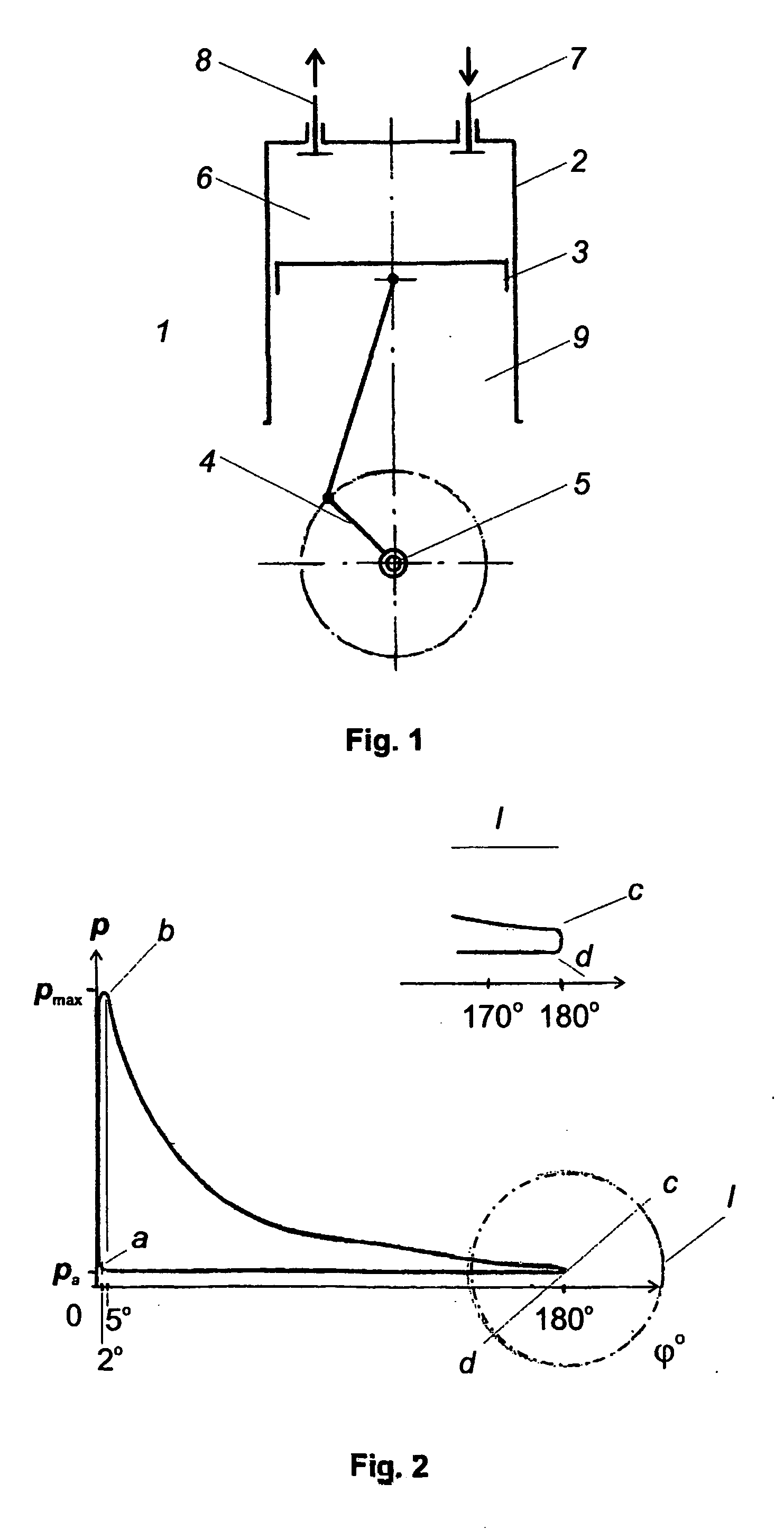
[0055] A one-stage one-sided supply pneumatic piston engine shown in FIG. 1 contains the following construction elements: 1--PPE, 2--cylinder, 3--piston, 4--crank, 5--crankshaft, 6--working chamber (over-cylinder space), 7--means for supply of compressed air (inlet valve), 8--means for exhaust of air (outlet valve), 9--under-cylinder space.

[0056] A PPE shown in FIG. 1 consists of a cylinder 2 containing a piston 3 kinematically joined via a crank 4 to crankshaft 5, and a working chamber 6 (over-cylinder space). The working chamber 6 contains a means 7 for supply of compressed air to the working chamber arranged as an inlet valve and a means 8 for exhaust of air, while the piston is in the region of bottom dead center, arranged as an outlet valve. The under-cylinder space 9 is bridged to atmosphere. The means 7 for supply of compressed air may be joined to an external source of compressed air.

[0057] The device according to the invention operates a...


PUM


Abstract

The present invention concerns a method for operating and arrangement of a pneumatic piston engine. The pneumatic piston engine (1) includes a cylinder (2) including a piston (3) kinematically joined via a crank (4) to a crankshaft (5) and a working chamber (6) supplied with a means (7) for supply of compressed air and a means (8) for exhaust of air. The starting of supply of compressed air is realized while the piston (3) is in the region within the range from 40° before top dead center to 25° after top center by angle of rotation o the crank of the crankshaft depending on engine speed, and the ending of supply is realized while the piston (3) is in the region within the range from 0° to 90° after top dead center by angle of rotation of the crank of the crankshaft. In particular case when engine speed is 2.12 s<-1>, the optimum mode of operating is achieved provided that supply of compressed air starts when the piston (3) is in position of 2° before the top dead center and ends when the piston (3) is in position of 5° after the top dead center by angle of rotation of the crank of the crankshaft. The invention provides decrease of specific fuel consumption approximately by a factor of 5-6 and simultaneous increase of the piston specific power.

Description

[0001] The present invention relates to the field of engineering industry, in particular engine building, namely pneumatic piston engines (PPE). The invention can be used at transport in power drives and in power generation.[0002] High power consumption is the main problem of present-day transport. That is the reason why experts in the field of transport engineering face a task to provide speeds being adequate to up-to-date requirements with simultaneous increasing piston specific power of the engine and decreasing specific fuel consumption.[0003] Internal combustion engines (ICE) make up the bulk of the present-day transport engines. Increase of transport speed requires increasing engine power density. However, raise of engine power density in present-day ICEs is obstructed by high temperature in the working chamber of the engine and resulting thermo stress, as well as low reliability and low life of engine. Among other ICE disadvantages, one may point to its complex construction, ...

Claims


Application Information

Patent Timeline
Patent Type & Authority Applications(United States)
IPC IPC(8): F01B17/02F01B29/10
CPCF01B17/02F01B29/10
Inventor BOGOMOLOV, YURYFELDMAN, JURL
Owner BOGOMOLOV YURY
Why Eureka
Try Eureka