
Option for independently adjusting the timing of the forward and reverse direction of bi-directional digital signals

Inactive Publication Date: 2004-11-25
SIEMENS AG
View PDF4 Cites 7 Cited by
  • Summary
  • Abstract
  • Description
  • Claims
  • Application Information

AI Technical Summary

Benefits of technology

[0014] The invention enables a delayed clocking in of the signals of the reverse direction without strobe signals also being supplied. By means of suitable delay lines on the board it is possible to set the signal clock-in timing for forward and reverse direction independently of each other. The timing of the entire bus system can also be adjusted. This enables the maximum frequency to be increased or the bus frequency to be operated with fewer restrictions. The design risk for the timing is considerably reduced because it can still be changed on the finished board by insertion of other delay lines.
[0015] The invention is based on the above described PLL clock system for minimizing clock skew. An important idea of the invention consists in the transmission of a further clock together with the output clock for the receivers and the feedback clock for the PLL. This further clock is looped back via a delay line and used for clocking in the signals in the reverse direction. Delay lines are also provided in the feedback clock of the PLL and in the receiver clock path. By insertion of different delay lines the times of clocking out and clocking in at the transmitter and the clock of the receivers can be set arbitrarily within limits (see FIG. 3).
[0016] Furthermore, the timing can be improved and external influences minimized by coupling the output signals to the output clock. This coupling is achieved as follows: the output data register is clocked not with the normal system clock for the core of the ASIC, but with the clock which is derived from the output clock of the PLL (see FIG. 4). Finally, in order to minimize external influences, buffer type and placing of clock and signal output buffers are implemented identically.
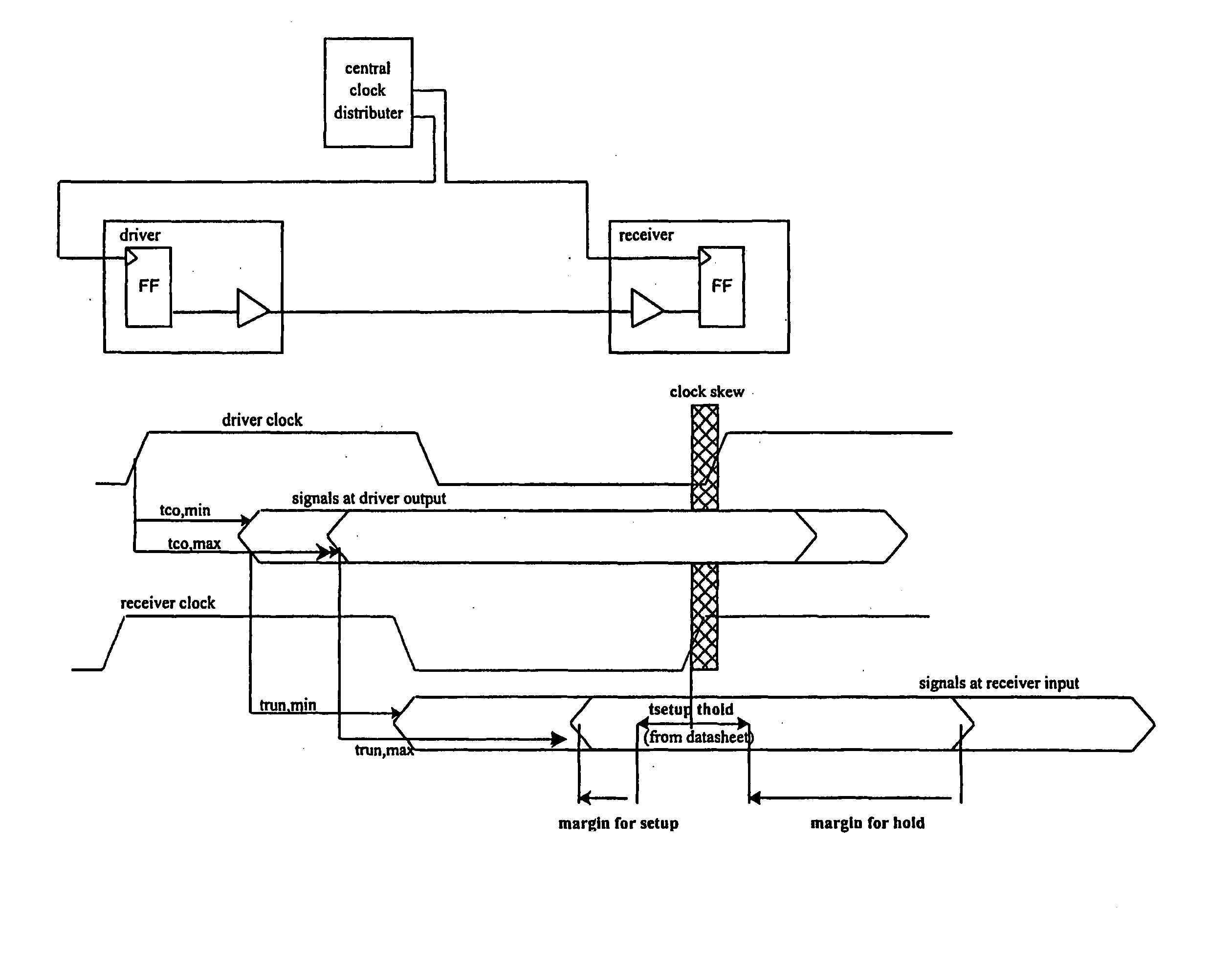
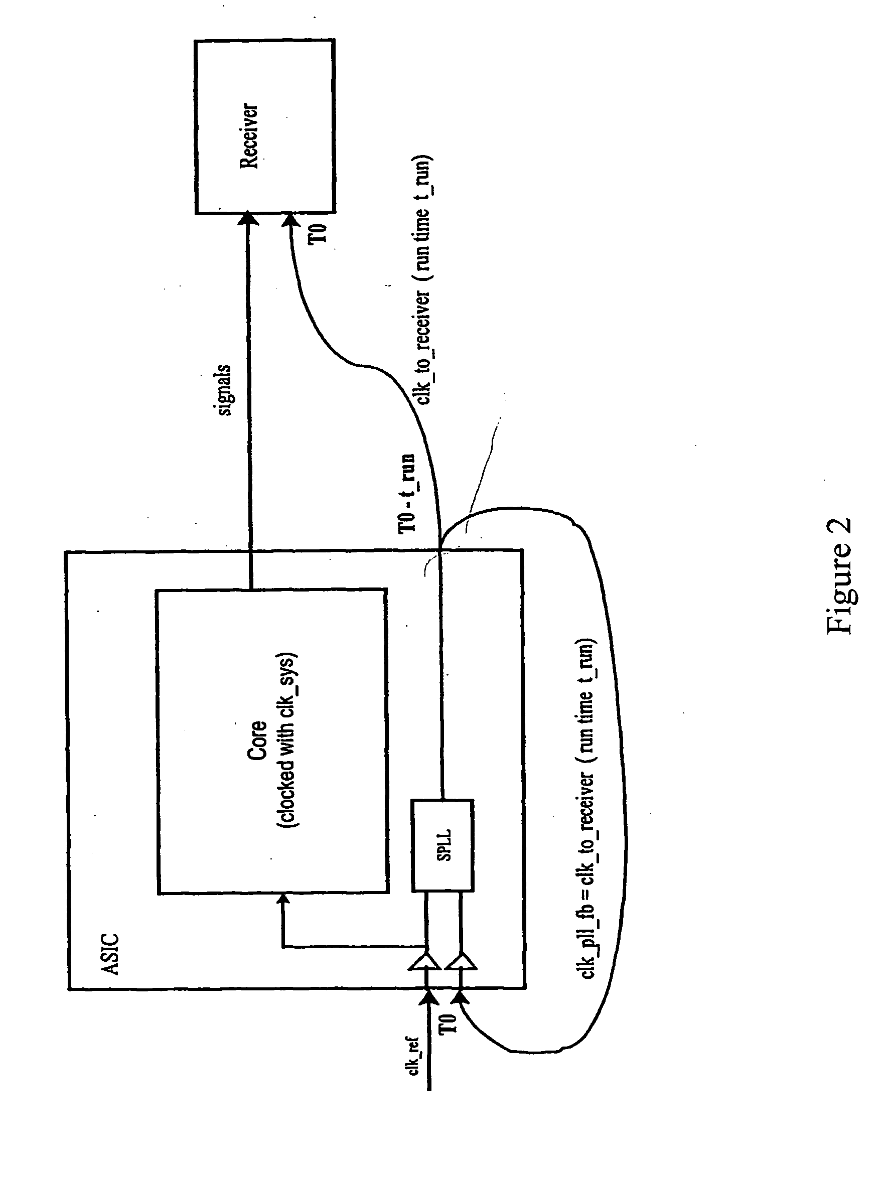
[0018] FIG. 2. shows an already partly common variant for minimizing the clock skew between transmitter and receiver using a PLL in the transmitter device,

Problems solved by technology

With bidirectional signals, the optimization is even more difficult.
On the other hand this probably gives rise to a problem with regard to the setup time.
With bidirectional signals this is impossible.
Each change in favor of one direction is detrimental to the timing of the other direction.
For simple digital circuits, no solution at all was found for this problem.

Method used


Image

  • Option for independently adjusting the timing of the forward and reverse direction of bi-directional digital signals
  • Option for independently adjusting the timing of the forward and reverse direction of bi-directional digital signals
  • Option for independently adjusting the timing of the forward and reverse direction of bi-directional digital signals

Examples


Embodiment Construction

[0021] The principle presented is realized by way of example in an SDRAM memory controller comprising an ASIC, 4.times.5 12 MB SDRAM DIMMs (see FIG. 4).

[0022] If the delay lines are initially regarded as not present, then all the clock edges at the ASIC input and at the DIMMs are locked in phase (TO).

[0023] The clock of the DIMMs can be shifted by means of delay 1. An increase means that the DIMM clock is leading, which serves to comply with the hold time. Coupling the output signals to the output clock ensures there is an adequate budget for setup compliance.

[0024] The clocking in of the reverse direction signals can be delayed by means of delay 2. Because the clock-to-output time for SDRAMs is relatively high at 5.6 ns (the entire clock period only has 7.5 ns!), this is very necessary.

[0025] The entire clock system can be shifted forward by means of delay 3.

[0026] In addition to the schematic circuit diagram shown in (3), a PLL clock driver is also installed. This multiplies the o...


PUM


Abstract

It is difficult to optimize the timing of the forward and reverse direction for high frequency bidirectional digital signals. The invention improves the adjustability of the timing by the emission of an additional clock pulse, together with the output clock pulse for the receiver and the feedback clock pulse for the PLL. Said additional clock pulse is re-circulated using a delay line and is used to set the clock pulse of the reverse direction signals.

Description

CROSS REFERENCE, TO RELATED APPLICATIONS[0001] This application is the US National Stage of International Application No. PCT / EP02 / 09694, filed Aug. 30, 2002 and claims the benefit thereof. The International Application claims the benefits of European application No. 01121401.2 EP filed Sep. 6, 2001, both of the applications are incorporated by reference herein in their entirety.[0002] The invention relates to a delayed clocking of signals in the reverse direction without strobe signals also being supplied. Additionally, the invention improves the adjustability of the timing by the emission of an additional clock pulse, together with the output clock pulse for the receiver and the feedback clock pulse for the PLL.BACKGROUND OF INVENTION[0003] The performance of digital systems is heavily dependent on the frequency. On the other hand, the higher the frequency, the shorter is the time remaining to convey digital signals reliably from a driver via a conductor track to the receivers. Li...

Claims


Application Information

Patent Timeline
IPC IPC(8): G06F1/04G06F1/10
CPCG06F1/10
Inventor HOHNEL, FALK
Owner SIEMENS AG
Learn More