Diaphragm structure of light sound converter
- Summary
- Abstract
- Description
- Claims
- Application Information
AI Technical Summary
Problems solved by technology
Method used
Image

Examples
Embodiment Construction
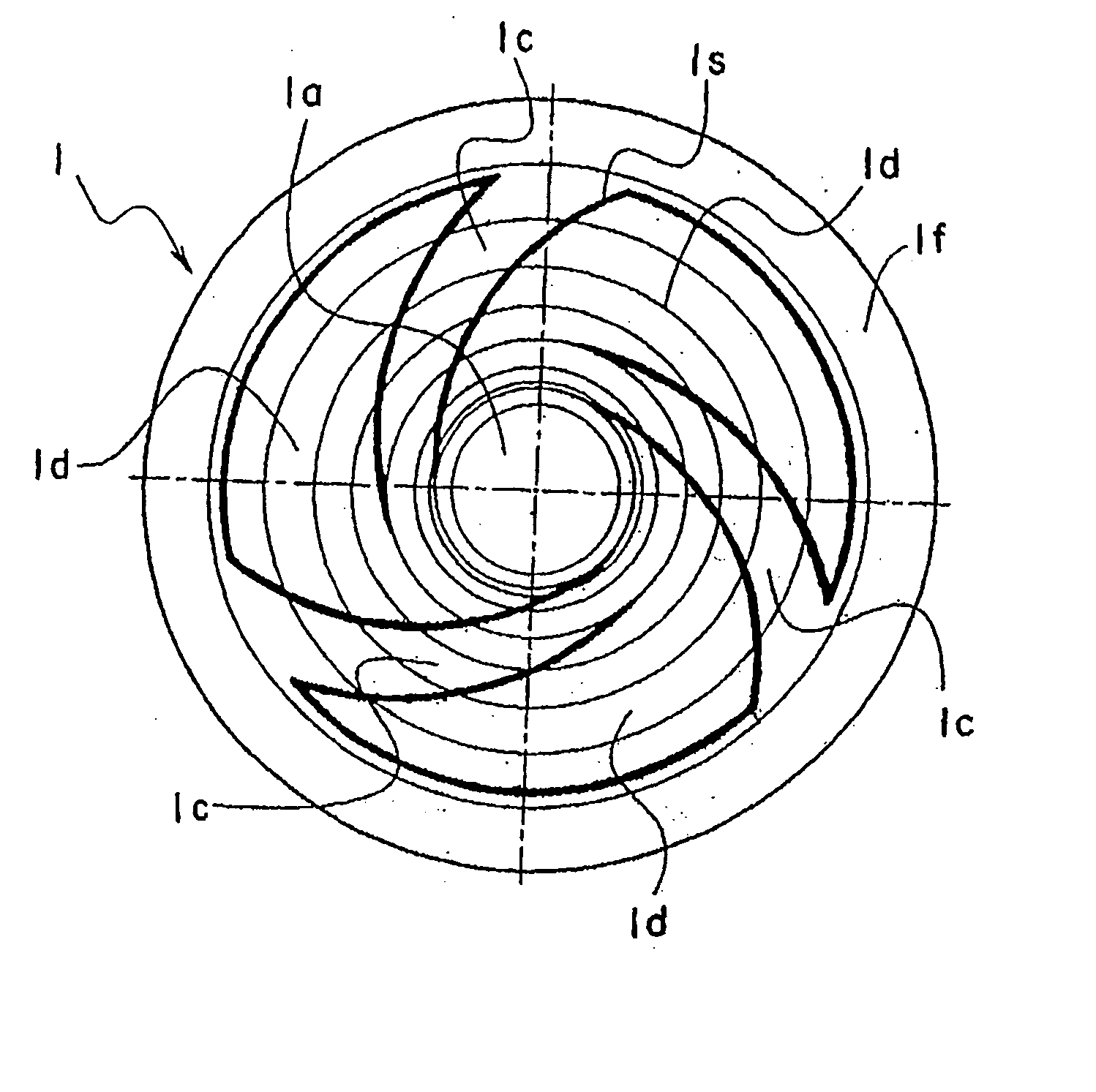
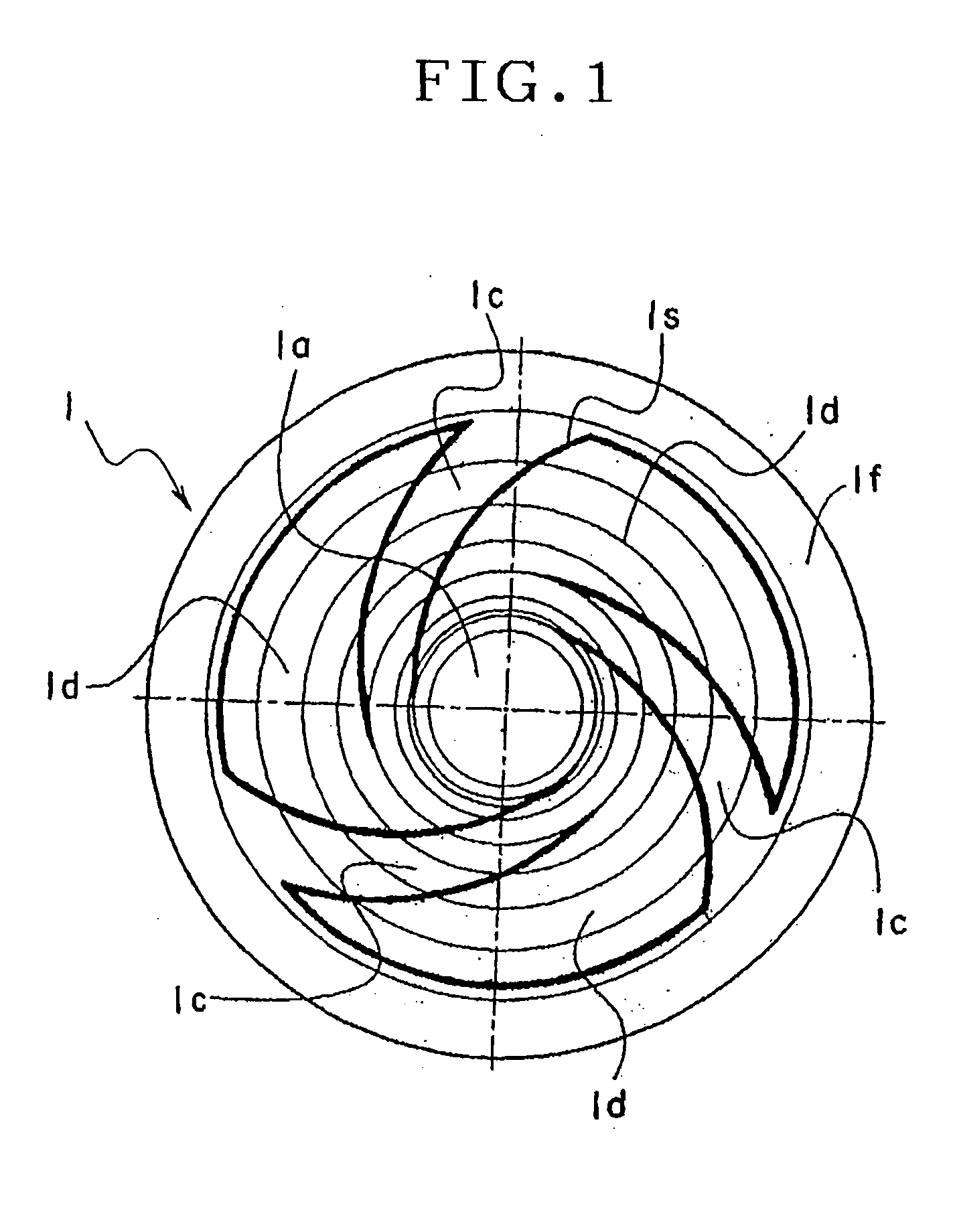
[0043] Embodiments of the invention will be described in detail. FIGS. 1 to 4 show examples of the structure of a diaphragm of a light sound converter according to the embodiments of the invention. In the embodiments, each diaphragm was formed by thermally molding a resin film having a thickness of about 9 .mu.m to about 16 .mu.m.
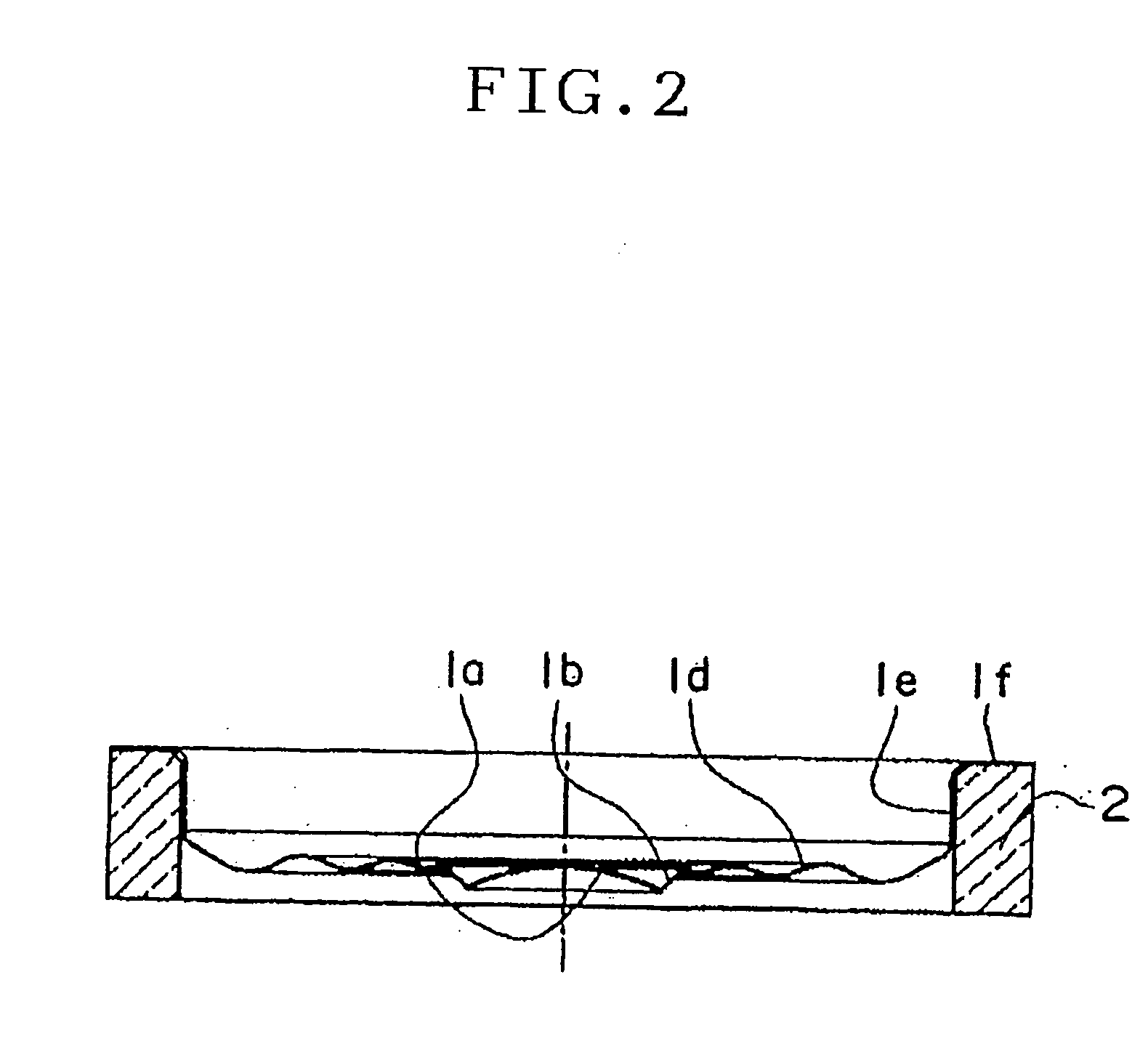
[0044] FIGS. 1 and 2 show the first embodiment of the invention. The fundamental shape of a diaphragm before slits 1s indicated by bold solid lines in FIG. 1 are formed is similar to that of the conventional diaphragm shown in FIGS. 7 to 9 before partial removal of the diaphragm by trimming molds. Referring to FIGS. 1 and 2, a dome shape reflective part 1a is formed in the central area of a diaphragm 1. The reflective part la has a diameter of 1.3 mm and a radius of curvature of 1.5 mm. A rising part 1b rising obliquely at 45.degree. is formed continuously with an outer peripheral area of the reflective part 1a. A suspension part 1c, 1d is formed integrally...
PUM
| Property | Measurement | Unit |
|---|---|---|
| Time | aaaaa | aaaaa |
| Width | aaaaa | aaaaa |
| Width | aaaaa | aaaaa |
Abstract
Description
Claims
Application Information
PatSnap Eureka turns technology decisions into work you can execute. Powered by our Innovation Knowledge Graph, it runs expert workflows across engineering, life sciences, materials and intellectual property. Get your review-ready output in minutes.


