Physical quantity monitoring and control system and portable information terminal used for the same

a technology of physical quantity monitoring and control system, applied in the direction of instruments, nuclear elements, nuclear engineering, etc., can solve the problem that the functions of pcs and portable information terminals are not effectively used

Inactive Publication Date: 2004-12-02
NEC CORP
View PDF13 Cites 19 Cited by
  • Summary
  • Abstract
  • Description
  • Claims
  • Application Information

AI Technical Summary

Benefits of technology

[0012] It is an object of the present invention to provide an environment condition monitoring and control system in which information on an environment which is transmitted from various sensors and / or information transmitting terminals which are disposed in a natural or artificial environment is collected by a PC or portable information terminal for operating various devices via a network, so that characteristics of the PC or portable terminal is effectively used.

Problems solved by technology

The functions of PCs and portable information terminals are not effectively used.

Method used


Image

  • Physical quantity monitoring and control system and portable information terminal used for the same
  • Physical quantity monitoring and control system and portable information terminal used for the same
  • Physical quantity monitoring and control system and portable information terminal used for the same

Examples


Embodiment Construction

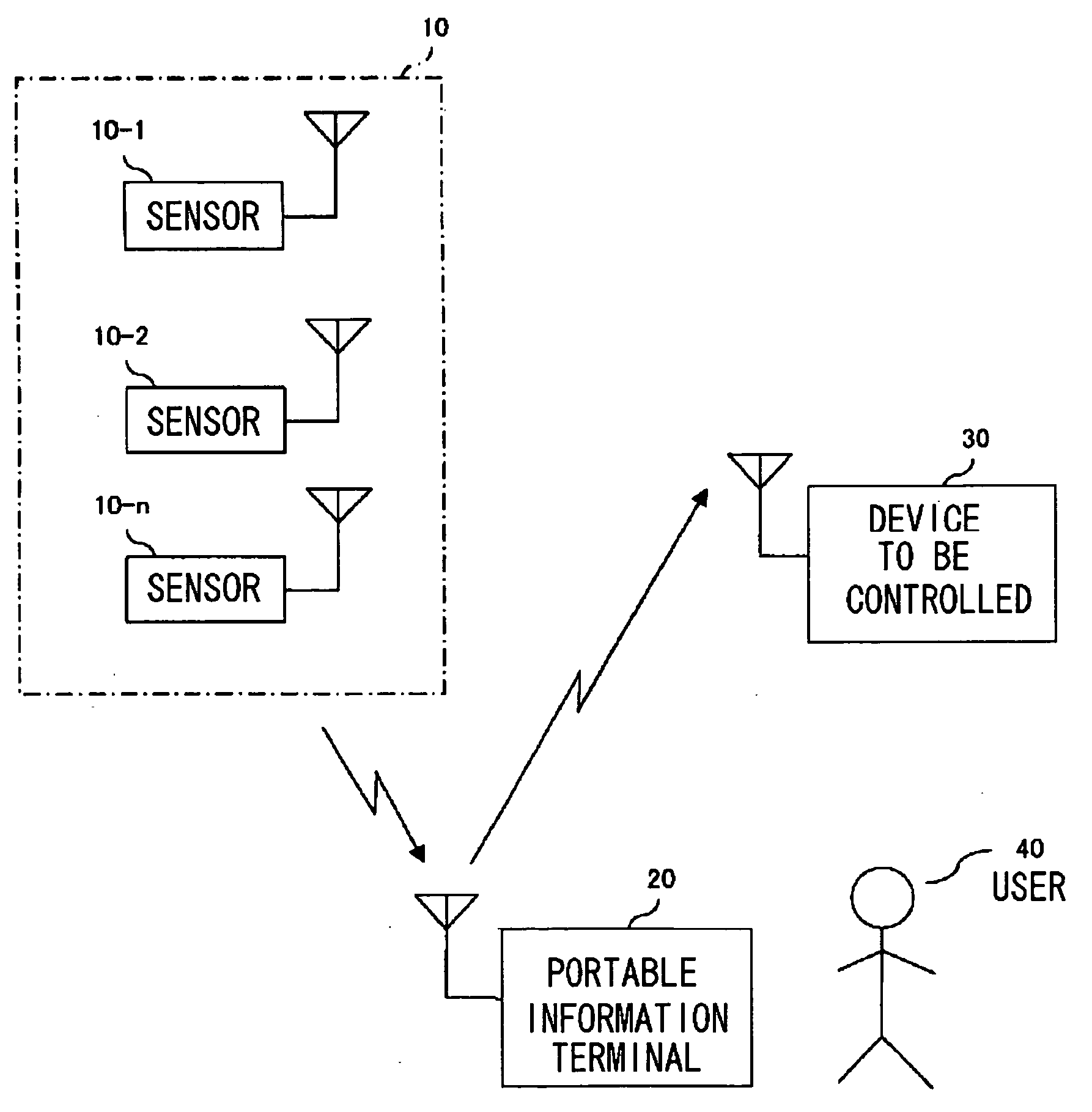
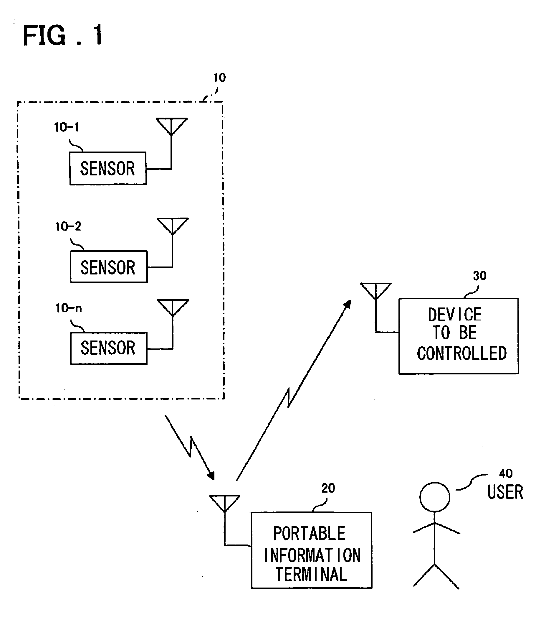
[0025] Now, embodiments of the present invention will be described with reference to drawings. FIG. 1 is a system block view showing an embodiment of the present invention. Referring now to FIG. 1, a sensor group 10 comprising sensors 10-1 through 10-n wherein n denotes a natural number are mounted indoors in predetermined positions. The sensors 10 are capable of monitoring and measuring physical quantities such as temperatures and luminosity for converting them into electrical data signals and for wirelessly transmitting them. They are referred to as self-contained transmission sensors. They have power sources such as solar cells incorporated therein.

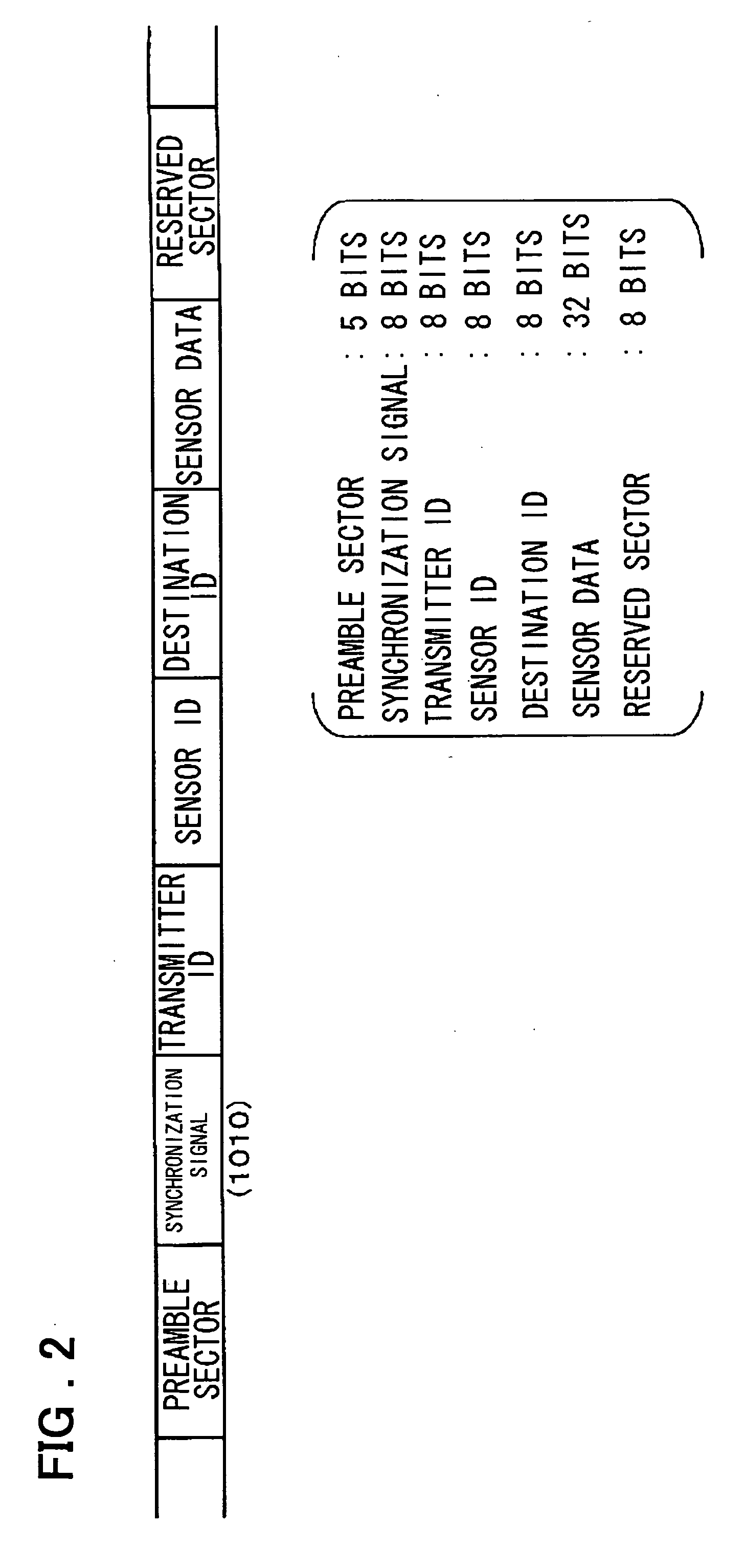
[0026] An electrical data signal which is transmitted by such a self-contained transmission sensor has such a frame format shown in FIG. 2 that it comprises a preamble sector, a synchronization signal sector for synchronization, a sensor ID which represents the kind of physical quantity which has been converted into a data signal, a tr...


PUM


Abstract

To enable indoor and outdoor physical conditions to be detected for very fine control thereof. Self-contained transmitting sensors 10-1 through 10-8 which monitor physical quantities and convert them into electrical data signals for radio-transmission are disposed in desired positions in housing. The wirelessly transmitted data signals are received by a portable information terminal 20 for controlling the operation of a device 30 to be controlled based upon the received information and its information history. By wearing a self-contained transmitting sensor 10-9 on a user 40 physical quantities such as temperature, humidity and illumination at a place in which the user is located can be controlled to desired values wherever the user moves.

Description

[0001] The present invention relates to an environment condition monitoring and control system and in particular to an environment condition monitoring and control system which monitors various conditions in a natural or artificial environment in building for controlling them.[0002] There are various systems which monitor natural and artificial environmental conditions for controlling them. For example, an air-conditioning system monitors the temperature and humidity in each room of building for controlling them at desired presettings. In such an air-conditioning system, the temperature and humidity of each room is monitored by sensors and the monitor results are transmitted to a central control unit at which a control signal for an air-conditioner in each room is generated for controlling the temperature and humidity in each room to desired values.[0003] In this case, the method of transmitting the monitor result of the temperature and the humidity in each room to the central contr...

Claims


Application Information

Patent Timeline
Patent Type & Authority Applications(United States)
IPC IPC(8): G01D4/00G08C17/00G06F15/00G08C17/02H04B7/26H04M11/00
CPCG01D4/006G08C17/02G08C2201/51H04W84/18Y02B90/243Y04S20/325Y02B90/246Y04S20/42Y02B90/20Y04S20/30
Inventor KOBAYASHI, IKUTARO
Owner NEC CORP
Why Eureka
Try Eureka