
Method for protecting a pneumatic control system from ingested contamination

a technology vacuum contamination, which is applied in the field of pneumatic control system protection, can solve the problems of long downtime of the cmp carrier head system, reduced response time and evacuation time of the pneumatic control system, and non-planar surfa

Inactive Publication Date: 2004-12-16
MKS INSTR INC
View PDF12 Cites 9 Cited by
  • Summary
  • Abstract
  • Description
  • Claims
  • Application Information

AI Technical Summary

Benefits of technology

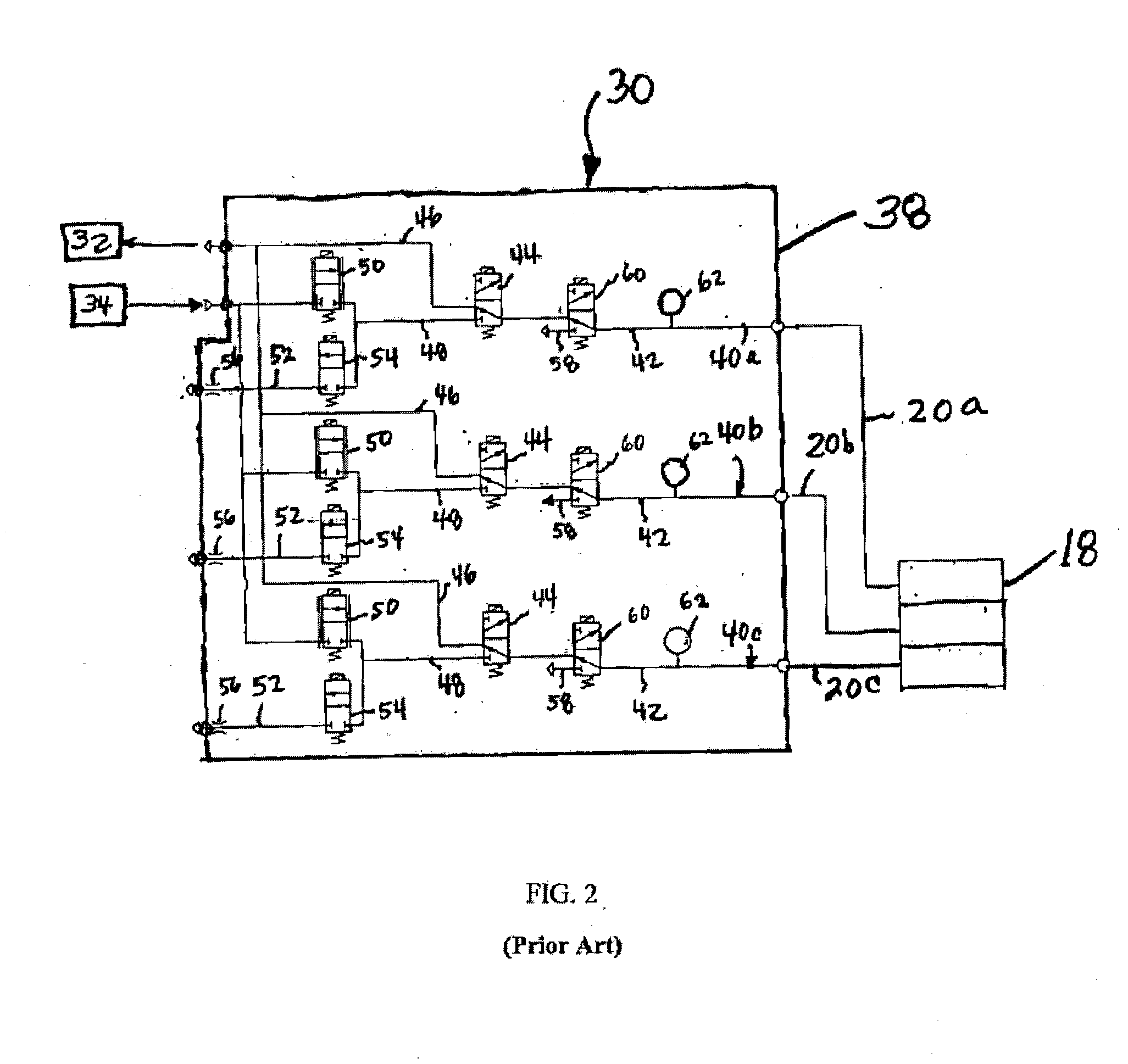
0013] The present disclosure provides a pneumatic control system including at least one flow control line having a connecting line connectable to a fluid line of a pneumatically operated machine, a vacuum line connectable to a vacuum source, a vacuum valve controlling flow between the connecting line and the vacuum line, a pressure line connectable to a source of fluid under pressure, and a pressure v

Problems solved by technology

This non-planar surface presents problems in the photolithographic steps of the integrated circuit fabrication process.
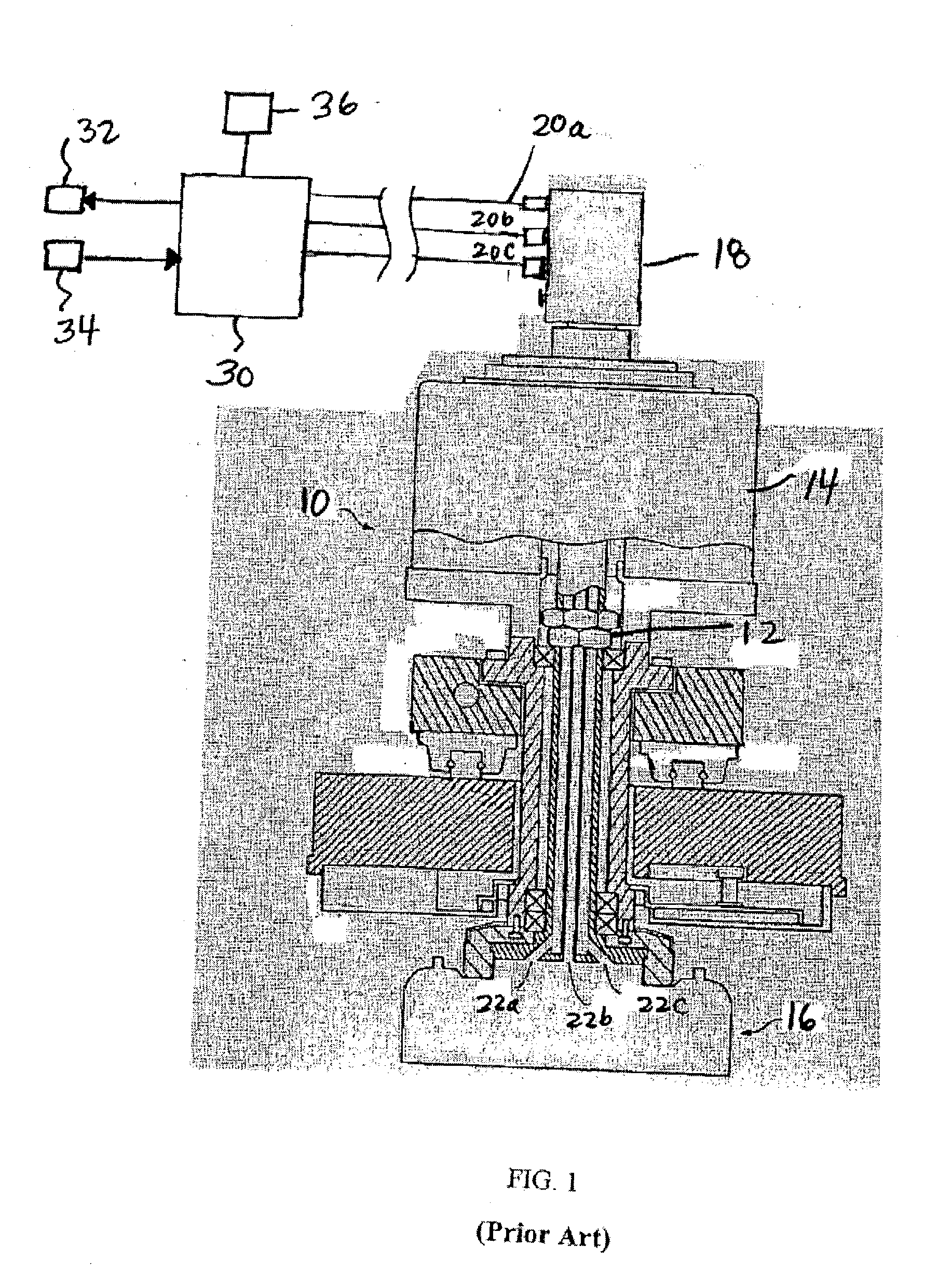
One problem associated with the pneumatic control system 10 of the prior art occurs when a vacuum is being created within the carrier head 16 during a CMP procedure, and a bladder in the carrier head 16 fails.
A bladder failure and subsequent replacement and recalibration of the pneumatic control system 30, in turn, can lead to a long downtime for the CMP carrier head system 10.
However, such filters have been found to reduce the response time and the evacuation time of the pneumatic control system 10.
When the vacuums are reduced or eliminated the substrate can be dropped and damaged or destroyed.

Method used


Image

  • Method for protecting a pneumatic control system from ingested contamination
  • Method for protecting a pneumatic control system from ingested contamination
  • Method for protecting a pneumatic control system from ingested contamination

Examples


Embodiment Construction

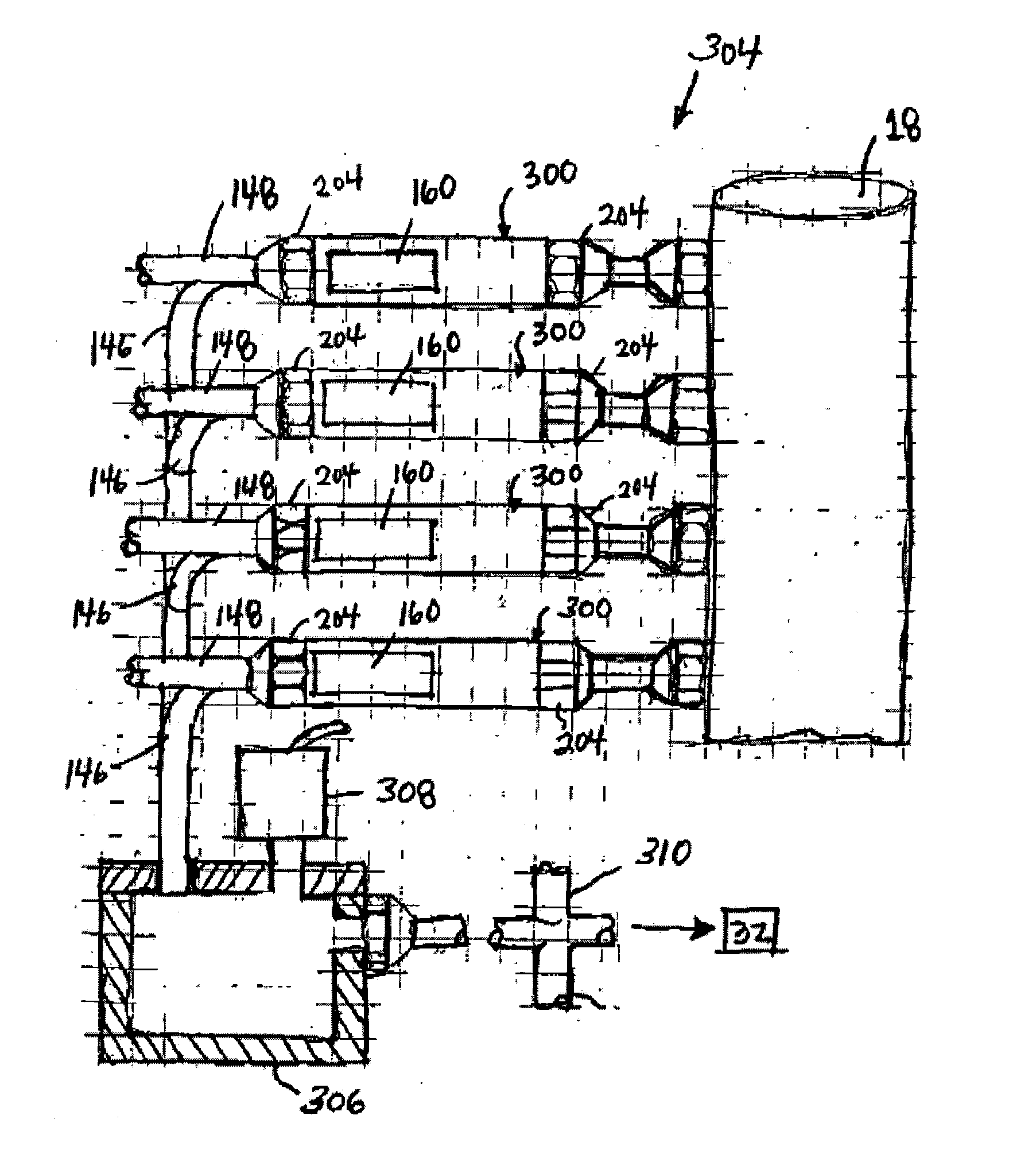
[0031] FIG. 3 is a schematic drawing of an exemplary embodiment of a pneumatic control system 100 constructed in accordance with the present invention and shown connected to a rotary union 18 of a CMP machine. However, it should be understood that the present invention is directed to the pneumatic control system 100 and not to a CMP machine, and it is intended that the pneumatic control system 100 of the present invention can be used with pneumatically-operated machines other than a CMP machine.

[0032] The pneumatic control system 100 includes a pressure manifold 102 defining pressure lines 48 of a plurality of flow control lines 140a-140c of the system 100. The pneumatic control system 100 also includes a plurality of vacuum manifolds 104, wherein each vacuum manifold 104 defines a vacuum line 146 of each of the flow control lines 140a-140c. The vacuum manifolds 104 are each adapted for replacement independently of the pressure manifold 102, and can be independent of the other vacuu...


PUM


Abstract

A pneumatic control system including at least one flow control line having a connecting line connectable to a fluid line of a pneumatically operated machine, a vacuum line connectable to a vacuum source, a vacuum valve controlling flow between the connecting line and the vacuum line, a pressure line connectable to a source of fluid under pressure, and a pressure valve controlling flow between the connecting line and the pressure line. A pressure manifold defines the pressure line and a first portion of the connection line, and supports the pressure valve, and a vacuum manifold defines the vacuum line and a second portion of the connecting line, and supports the vacuum valve. The vacuum manifold is adapted for replacement independently of the pressure manifold.

Description

FIELD OF THE DISCLOSURE[0001] The present disclosure relates generally to pneumatic control systems and more specifically to a pneumatic control system for pressurizing and evacuating semiconductor processing equipment. More particularly, the present disclosure relates to a method for protecting a pneumatic control system from vacuum contaminants.BACKGROUND OF THE DISCLOSURE[0002] Integrated circuits are typically formed on substrates, particularly silicon wafers, by the sequential deposition of conductive, semiconductive or insulative layers. After each layer is deposited, the layer is etched to create circuitry features. As a series of layers are sequentially deposited and etched, the outer or uppermost surface of the substrate, i.e., the exposed surface of the substrate, becomes increasingly non-planar. This non-planar surface presents problems in the photolithographic steps of the integrated circuit fabrication process. Therefore, there is a need to periodically planarize the su...

Claims


Application Information

Patent Timeline
IPC IPC(8): B24B37/005F16K37/00H01L
CPCB24B37/005Y10T137/8359F16K37/0066H01L21/6838H01L21/02
Inventor POULIN, JAMES M.CLARK, WILLIAM
Owner MKS INSTR INC
Learn More