
Method of managing the valves of a simulated moving bed separation system

a technology of moving bed separation and management method, which is applied in the direction of water supply installation, separation process, water/sewage treatment by ion exchange, etc., can solve the problems of high-frequency management of valves controlling injection and draw-off, extreme delicate and high-frequency management of valves, and impose relatively expensive materials for the seat of these valves

Inactive Publication Date: 2004-12-23
INST FR DU PETROLE
View PDF6 Cites 15 Cited by
  • Summary
  • Abstract
  • Description
  • Claims
  • Application Information

AI Technical Summary

Benefits of technology

The patent describes a method for managing the valves of a simulated moving bed separation system to improve the monitoring of a concentration profile. The system uses a closed loop with beds filled with adsorbent to separate components in a feedstock. The position of the injection points and the draw-off points of the feedstock, eluent, and extract or raffinate can be moved periodically to create a continuous flow of the system. The concentration profile of the various species present in the system is determined by the recirculation flow and the position of the injection and draw-off lines. The patent proposes a method to manage the valves to improve the purity of the product and the yield of the separation process.

Problems solved by technology

During the period, it is therefore all of the connections that are concerned by the displacement of the injection and draw-off points, which in practice leads to an extremely delicate and high-frequency management of the valves controlling injection and draw-off.
The constraint on the opening / closing time also imposes relatively costly materials for the seat of these valves which undergo shocks and have to withstand considerable mechanical wear.

Method used


Image

  • Method of managing the valves of a simulated moving bed separation system
  • Method of managing the valves of a simulated moving bed separation system
  • Method of managing the valves of a simulated moving bed separation system

Examples


case 1

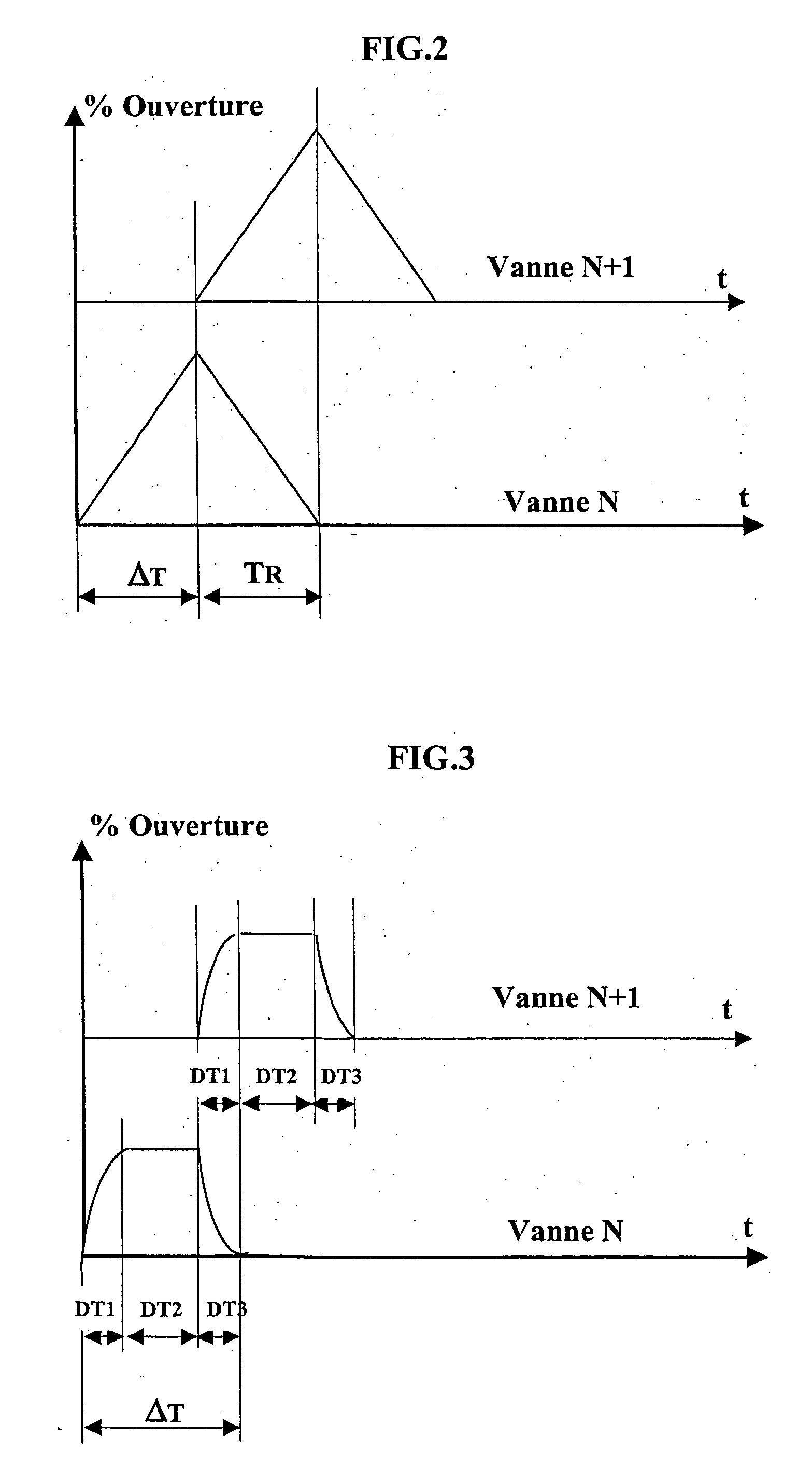
[0107] Case 1 corresponds to an opening law of the first order for which 99% of the valve opening is reached in 27.5 seconds, i.e. 36.7% of period .DELTA.T.

case 2

[0108] Case 2 corresponds to an opening law of the first order for which 99% of the valve opening is reached in 46 seconds, i.e. 61.3% of period .DELTA.T.

case 3

[0109] Case 3 corresponds to an opening law of the first order for which 99% of the valve opening is reached in 69 seconds, i.e. 92% of period .DELTA.T.


PUM

PropertyMeasurementUnit
opening timeaaaaaaaaaa
overlap timeaaaaaaaaaa

Abstract

A method of managing the valves of a simulated moving bed separation system comprising at least one column of adsorbent beds split into several zones delimited by injection and draw-off points, allowing finer monitoring of a determined concentration profile. The method comprises, during each period between the shift times of the injection and draw-off points, in opening and closing a first valve located at one end of a zone according to a determined law, while opening and closing the valve downstream from the first valve in relation to the direction of flow of the recirculation flow, according to the same law with a lag, referred to as overlap time, in relation to the first valve, which is less than or equal to the period, the law imposing a constant total flow rate for the flow passing through the two consecutive valves throughout the overlap time. Applications are any simulated moving bed separation system, preferably those used for relatively small-tonnage production such as fine petrochemistry, pharmaceutical industry, certain food processing industries, etc.

Description

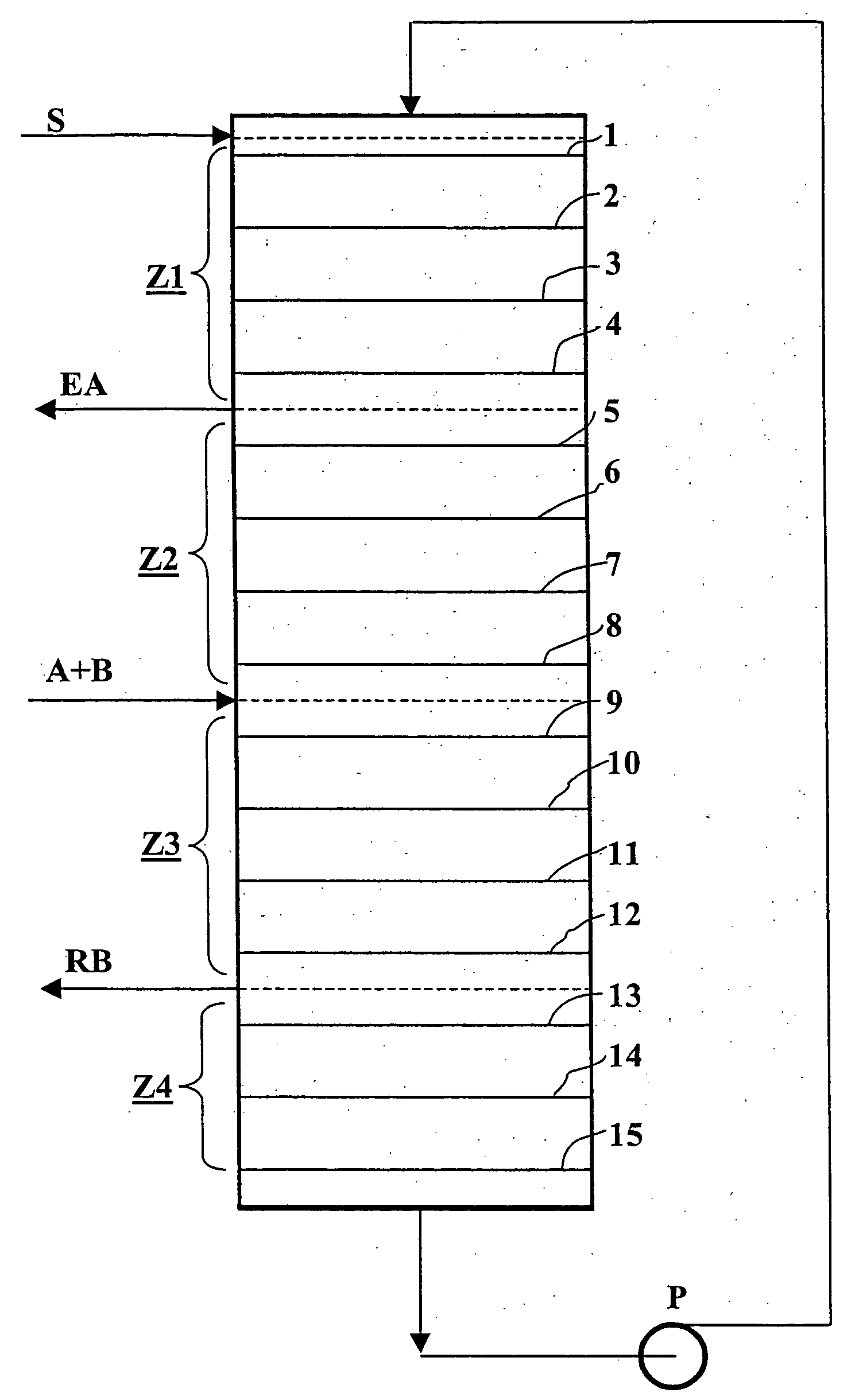
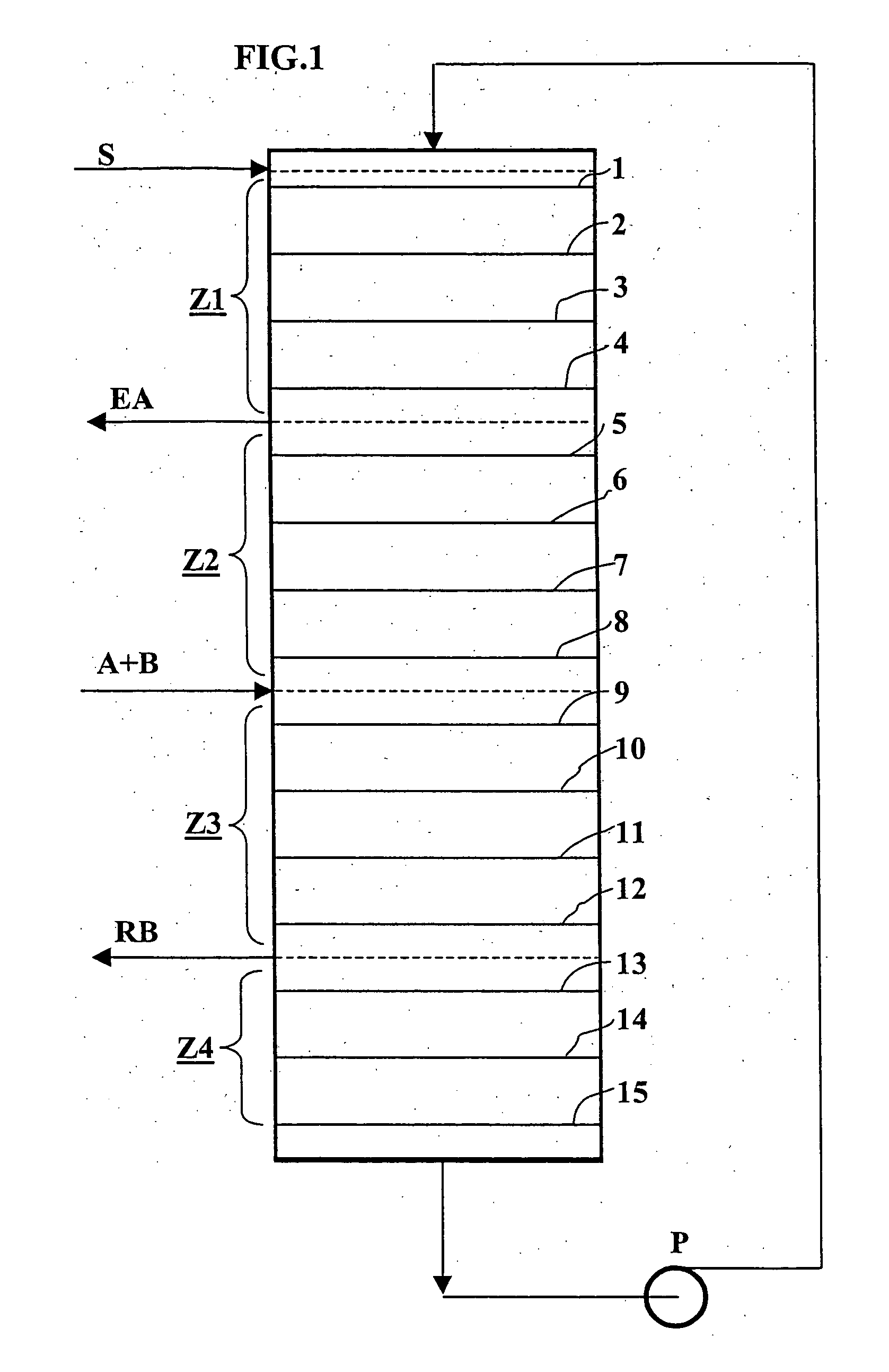
[0001] 1. Field of the Invention[0002] The invention relates to a method of managing the valves of a simulated moving bed separation system, allowing finer monitoring of a determined concentration profile.[0003] 2. Description of the Prior Art[0004] As already described in French patent 2,762,793 filed by the assignee, a simulated moving bed (SMB in abbreviated form) separation system, also referred to as simulated countercurrent (SCC in abbreviated form) separation system, comprises (FIG. 1) a series of beds filled with adsorbent which are arranged in a closed loop. A fluid circulation is established through this loop. The loop or column is divided into a succession of zones (Z1 . . . Z4), generally four, each zone consisting of a certain number of beds. Lines are connected to the loop between the various zones, allowing injection of a feedstock (A+B) at least one of the components of which is to be separated and of an eluent (S) which mainly contains the desorbent, or draw-off of ...

Claims


Application Information

Patent Timeline
Patent Type & Authority Applications(United States)
IPC IPC(8): B01D15/18B01D15/08
CPCB01D15/1828B01D2215/024Y10T137/0357B01D15/08
Inventor PAVONE, DIDIER
Owner INST FR DU PETROLE
Learn More