Liquid-crystal display device, compensator layer and method of manufacturing retardation foil

a technology of liquid crystal display device and compensator layer, which is applied in the direction of polarising element, chemistry apparatus and processes, instruments, etc., can solve the problems of redundant treatment with electric fields to induce tilt of display device, and great angle dependence of display device comprising such a compensator

Inactive Publication Date: 2004-12-23
KONINKLIJKE PHILIPS ELECTRONICS NV
View PDF1 Cites 14 Cited by
  • Summary
  • Abstract
  • Description
  • Claims
  • Application Information

AI Technical Summary

Benefits of technology

[0015] In a liquid-crystal display device in which the customary voltage is applied across the liquid-crystal material in the on-state, the directors in this material actually still make a small angle with the direction perpendicular to the substrates. As a result, the birefringence is different at different viewing angles and non-symmetrical with respect to a direction perpendicular to the two substrates, which explains the angle-dependence of a liquid crystal having a nematic structure. This birefringence is caused, as it were, by two partial layers of a liquid-crystal material in which the optical properties of a partial layer are governed by the average tilt angle in the relevant partial layer with respect to the substrates and by the average direction of orientation; if a sufficiently high voltage is applied across the liquid-crystal layer, then the average direction of orientation in the partial layer is approximately equal to the direction of orientation, as determined by the orientation layers on the substrate, so that the magnitude of the difference between the directions of orientation of the two partial layers is practically equal to the tilt angle. In accordance with the invention, the angle-dependence can be substantially eliminated by causing the average directions of orientation of the liquid-crystal molecules in the polymerized liquid-crystalline material of the retardation foils to intersect each other at an angle which is practically constant (for example equal to the twist angle of the display cell). The tilt angles of the liquid-crystal molecules in the polymerized liquid-crystalline material can be set relative to the substrates, such that the compensator composed of the retardation foils compensates the angle-dependence of the cell substantially completely.
[0018] For the reactive group use can be made of vinyl ethers, thiolene systems or epoxy groups. However, use is preferably made of reactive groups in the form of (meth)acrylate groups. Monomers comprising a(n) (meth)acrylate group proved to be excellently processable. In principle, the monomers can be thermally polymerized. In practice, radical-polymerization under the influence of actinic radiation, in particular UV light, is the simplest way of polymerizing the monomers. This has the advantage that persons skilled in the art can choose the temperature at which the mixture should be polymerized themselves. The choice of the temperature is often very important as the liquid-crystalline properties of the mixture to be polymerized are governed to a substantial degree by the temperature.
[0019] Preferably, the mixture to be polymerized also comprises monomers having two or more reactive groups of the above-mentioned type. During polymerization, the presence of such monomers leads to the formation of a three-dimensional network. This causes the optical properties of the inventive retardation foil to become less sensitive to variations in temperature. In particular for foils which are employed at different temperatures, such a small temperature-dependence of the optical properties is very favorable.

Problems solved by technology

However, display devices comprising such a compensator still have a great angle-dependence; this is to be understood to mean that the contrast is governed to a substantial degree by the angle or direction from which the display device is viewed.
Consequently, in this case treatments with electric fields to induce said tilt are redundant.

Method used


Image

  • Liquid-crystal display device, compensator layer and method of manufacturing retardation foil
  • Liquid-crystal display device, compensator layer and method of manufacturing retardation foil
  • Liquid-crystal display device, compensator layer and method of manufacturing retardation foil

Examples


Embodiment Construction

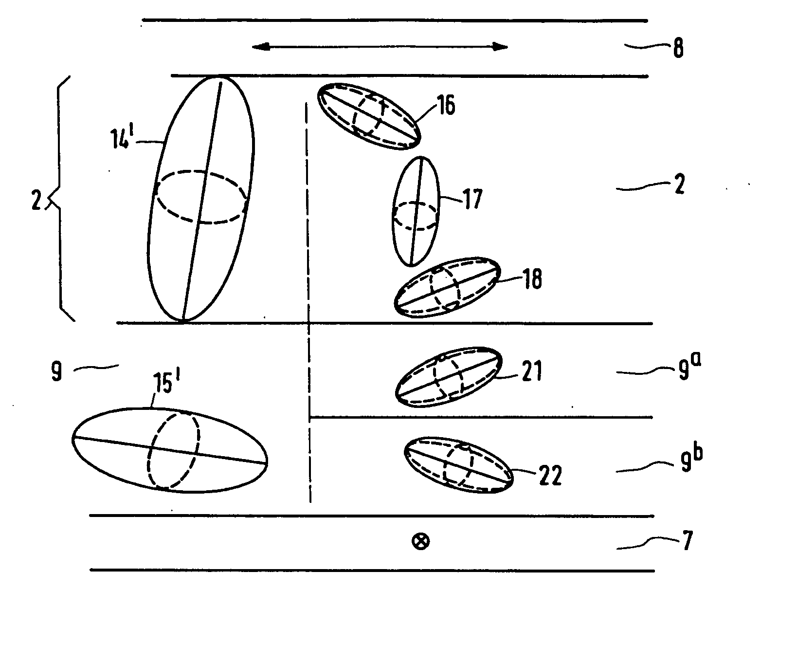
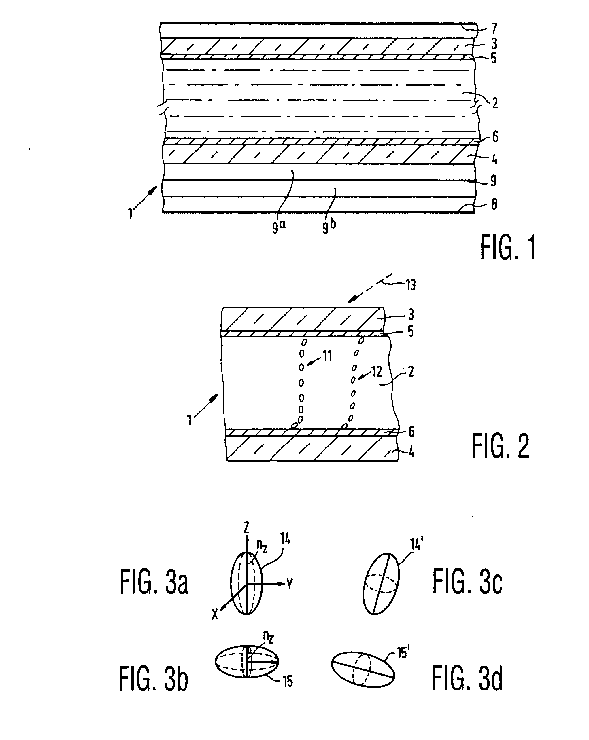
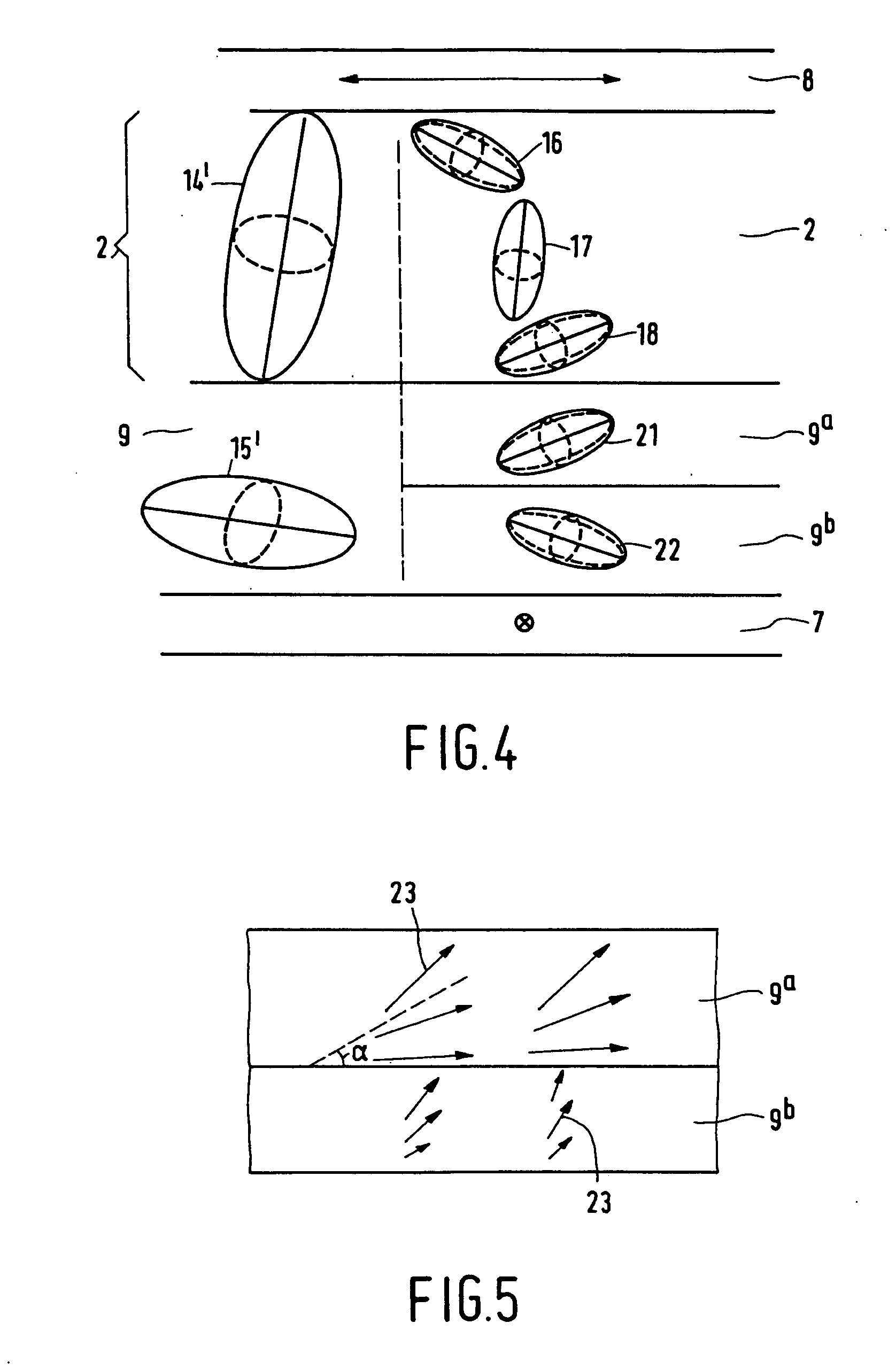
[0037] FIG. 1 is a schematic, cross-sectional view of a part of a liquid-crystal display device comprising a liquid-crystal cell 1 with a twisted nematic, liquid-crystal material 2 sandwiched between two substrates 3, 4, for example, of glass, which are provided with electrodes 5, 6. The device further comprises two polarizers 7, 8 whose directions of polarization intersect each other at right angles. The cell further includes orientation layers (not shown), which orient the liquid-crystal material on the inner surfaces of the substrates, in this example, in the direction of the polarization axes of the polarizers, so that the cell has a twist angle of 90 degrees. In this case, the liquid-crystal material has a positive optical anisotropy and a positive dielectric anisotropy. If a voltage is applied to the electrodes 5, 6, the molecules and hence the directors are oriented in accordance with the field. Thus, in an ideal case, all molecules extend substantially perpendicularly to bot...


PUM

PropertyMeasurementUnit
twist angleaaaaaaaaaa
angleaaaaaaaaaa
tilt angleaaaaaaaaaa

Abstract

A method of forming a liquid-crystal display device having a display cell comprises forming retardation foils on substrates using polymerized or vitrified liquid-crystal material wherein the liquid-crystal molecules of the polymerized or vitrified liquid-crystal material have a tilt angle with respect to a plane parallel to the substrates and so that the retardation foils have substantially complementary indicatrices and so that each one of the retardation foils brings about the compensation of approximately half the display cell in the driven state.

Description

[0001] The present application is a divisional of U.S. patent application Ser. No. 08 / 857,756 filed on May 15, 1997 in the name of Peter Van De Witte et al., the entire contents of which are hereby incorporated by reference.[0002] 1. Field of the Invention[0003] The invention relates to a liquid-crystal display device having a display cell which comprises a layer of a nematic, liquid-crystal material between two substantially parallel substrates, which display cell is further provided with polarizers. The invention further relates to a compensator layer which can be used, for example, in liquid-crystal display devices, and to a method of manufacturing a retardation foil.[0004] 2. Description of the Related Art[0005] Liquid-crystal display devices are generally used, for example, in monitors, TV applications and, for example, display devices in motorcars and for measuring instruments. The retardation foils can also be used in electro-optical modulators, for example, in welding goggle...

Claims


Application Information

Patent Timeline
Patent Type & Authority Applications(United States)
IPC IPC(8): C09K19/38G02B5/30G02F1/13G02F1/1335G02F1/13363
CPCG02B5/3016G02B5/3083G02F1/133632G02F1/1396G02F2413/105C09K19/38G02F1/13
Inventor VAN DE WITTE, PETERVAN HAAREN, JOHANNES A. M.M.HIKMET, RIFAT A.M.BROER, DIRK J.
Owner KONINKLIJKE PHILIPS ELECTRONICS NV
Why Eureka
Try Eureka