Vehicle braking control device for braking force distribution

a technology of braking control and control device, which is applied in the direction of vehicle components, process and machine control, computation using non-denominational number representation, etc., can solve the problems of short total braking force on the vehicle body, front wheel is more prone to enter into the locked condition than the rear wheel, etc., to reduce the effect of braking force distribution control, prevent the braking force on the vehicle, and reduce the braking pressure on the front wheel

Inactive Publication Date: 2004-12-23
ADVICS CO LTD
View PDF12 Cites 10 Cited by
  • Summary
  • Abstract
  • Description
  • Claims
  • Application Information

AI Technical Summary

Benefits of technology

[0009] According to the present invention, there is provided a novel braking control device for a vehicle executing BFD control compatible with ABS control. A vehicle equipped with the control device has front and rear wheels, a braking system including braking force generating apparatuses provided for the respective wheels; at least a sensor monitoring an operational condition of the vehicle including a detector detecting an amount of braking action by a driver of the vehicle. In response to a variation of the operational condition monitored by the sensor, the control device executes BFD control in which braking force on the rear wheels is lowered in comparison with that on front wheels while the braking force on the front wheels is increased based upon an increment of the braking action amount by the driver detected by the detector. Namely, further increase in the braking action after the starting of BFD control is reflected in the front wheel braking force. Upon starting anti-skid control for either of the wheels during the execution of BFD control, however, an increment of the front wheel braking forces to be requested by BFD control is decreased.
[0010] As described above, the restriction of rear wheel braking forces would render the total braking force on a vehicle body short. Thus, preferably, the inventive BFD control device not only restricts the increase of braking force on the rear wheels by holding the rear wheel cylinders at a holding pressure determined based upon vehicle's running conditions (e.g. by dosing valves in the lines to the rear wheel cylinders), but also increases braking force on the front wheels for compensating the shortage of the rear wheel braking force and ensuring the generation of total force to be applied on a vehicle body. The increment of the front wheel pressure may be determined as a function of the restricted amount of the braking force on the rear wheels so as to render the resultant force increment on the front wheel equal to the force decrement on the rear wheels. Thus, the total braking force on the vehicle body can be rendered in conformity with the amount requested by a driver of the vehicle without the locking of the rear wheels and instability in the vehicle attitude induced therefrom.
[0011] Further, because of BFD control biased to front wheels, a front wheel is more liable to enter into the locked condition than a rear wheel. Thus, usually, ABS control starts for either of front wheels, first. Under such a condition, since no longer preferable is BFD biased to the front wheels, the increment of the front wheel braking force requested by BFD control will be reduced. Preferably, the process of reduction of the increment is executed gradually, avoiding abrupt variation of the front wheel braking force that would deteriorate the stability of the running condition of the vehicle; and excessive reduction of the deceleration of a vehicle which would render a driver anxious. Further, preferably, the reduction of the increment is executed irrespective of the braking action by the driver (the increment for the front wheel is determined based upon the driver's operation under a normal BFD control.).

Problems solved by technology

As described above, the restriction of rear wheel braking forces would render the total braking force on a vehicle body short.
Further, because of BFD control biased to front wheels, a front wheel is more liable to enter into the locked condition than a rear wheel.

Method used


Image

  • Vehicle braking control device for braking force distribution
  • Vehicle braking control device for braking force distribution
  • Vehicle braking control device for braking force distribution

Examples


Embodiment Construction

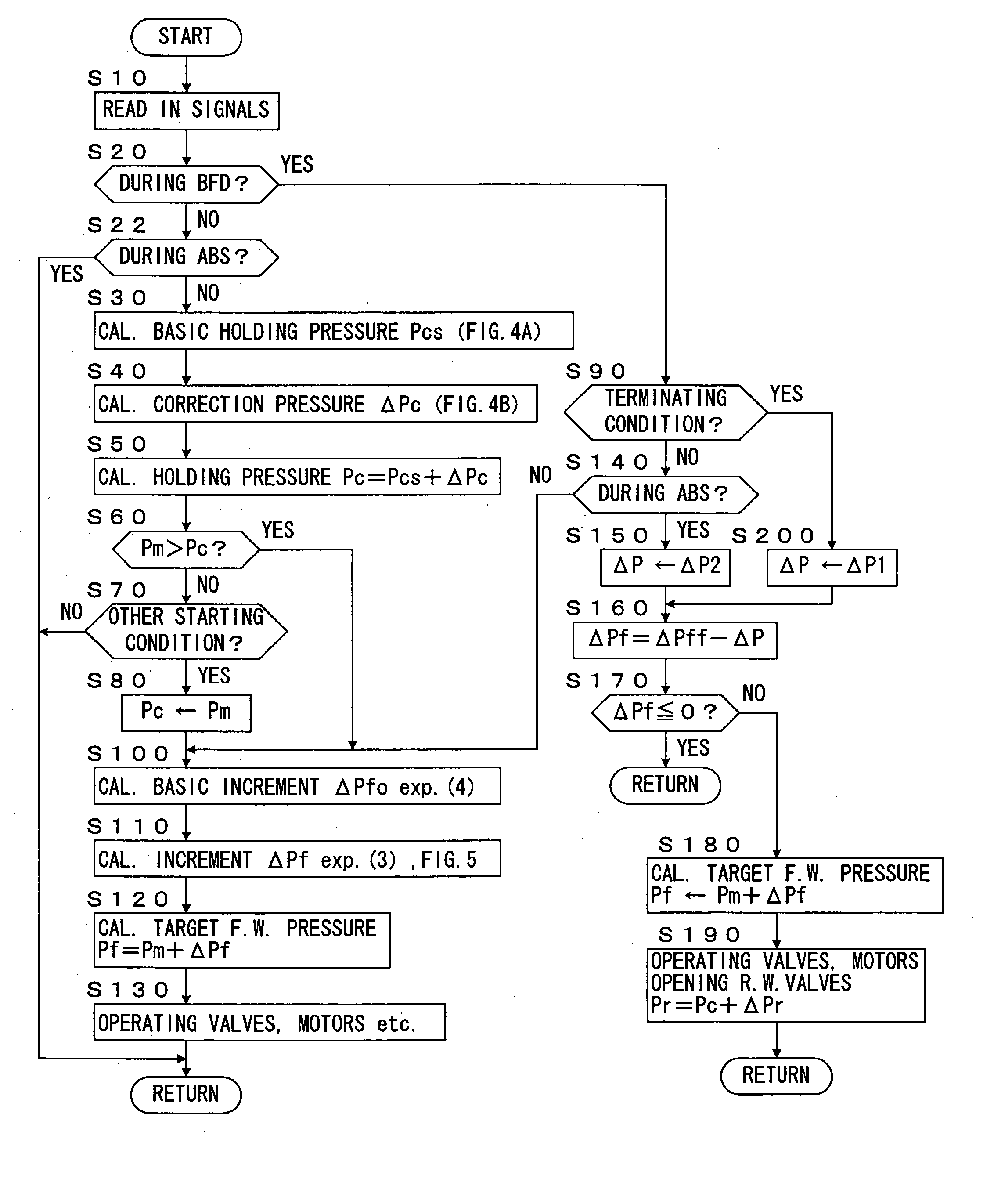
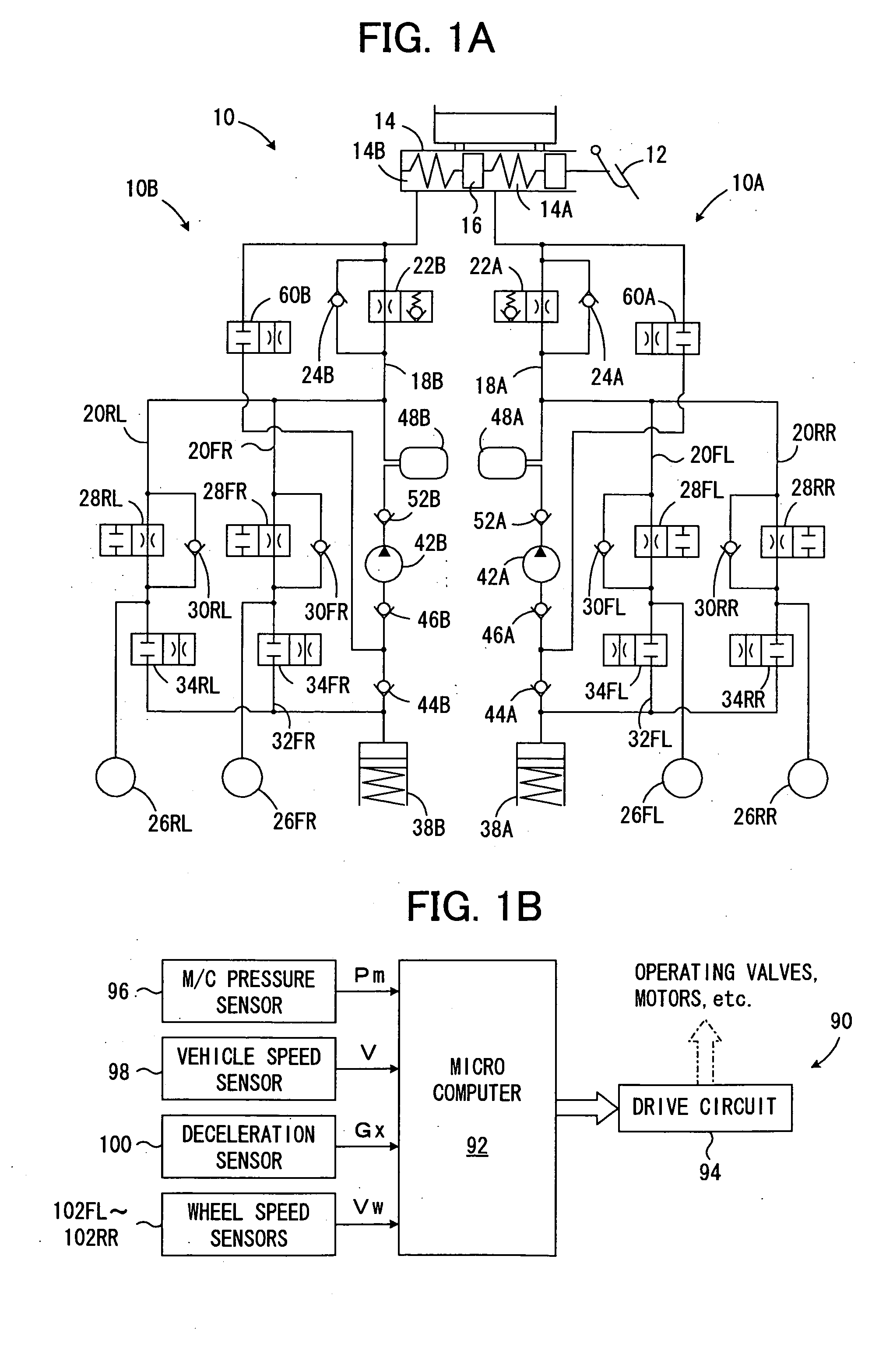
[0038] FIG. 1 illustrates a schematic diagram of a braking system implementing an embodiment of a control device for controlling braking force for a vehicle, enabling BFD control according to the present invention, which braking system consists of a hydraulic circuit 10 (FIG. 1A), transmitting a pressure in a master cylinder 14 (master cylinder pressure) to wheel cylinders 26i (i=FL, FR, RL, RR=front-left, front-right, rear-left and rear-right wheels, respectively) in braking force generating apparatuses provided for the respective wheels (not shown), and an electronic controller 90 (FIG. 1B) controlling brake fluid flows in the hydraulic circuit by operating solenoid valves and other components therein.

[0039] Referring to FIG. 1A, the illustrated hydraulic circuit 10 are of X dual circuit type, having two circuits, the one 10A for a pair of front left and right wheel cylinders 26FL, 26RR and the other 10B for a pair of rear left and right wheel cylinders 26FR, 26RL. It should be no...


PUM


Abstract

A braking control device for a vehicle executes braking force distribution (BFD) biased to front wheel in a manner compatible with Anti-skid control. In BFD control, braking force on rear wheels is held at a holding braking force and braking force on the front wheels is incremented beyond braking force requested by a braking action of a driver. After the starting of BFD control, further increase in the braking action is reflected in the front wheel braking force. Upon starting anti-skid control for either of the wheels during the execution of BFD control, an increment of the front wheel braking forces to be requested by BFD control is gradually decreased. Simultaneously, the holding of the rear braking force is released so as to compensate for the shortage of braking force on the front wheel. The gradual decrease of the braking force increment prevents a conflict of BFD and Anti-skid control.

Description

[0001] 1. Field of the Invention[0002] The present invention relates to a device for controlling brakes of a vehicle such as an automobile, and more specifically, to such a device that controls braking force distribution among front and rear wheels in a vehicle.[0003] 2. Description of Prior Art[0004] During braking of a vehicle, a rear wheel is liable to be locked because its frictional circle is shrunk due to the forward shifting of the load of the vehicle. The locking of a rear wheel, prior to a front wheel, induces serious deterioration of a vehicle running behavior, such as disturbance in the attitude and / or spinning of a vehicle body. In order to avoid the locking of a rear wheel, braking force distribution (BFD) control has been proposed to keep braking force on rear wheels lower than on the front wheels. In such BFD control, braking pressures applied to rear wheel cylinders in a hydraulic braking system is held, reduced or pulsatively increased, i.e. the increase in braking ...

Claims


Application Information

Patent Timeline
Patent Type & Authority Applications(United States)
IPC IPC(8): B60T8/1761B60T8/1766B60T8/26B60T8/40B60T8/58B60T8/88
CPCB60T8/17616B60T8/1766B60T8/268B60T8/4072B60T8/4872B60T8/885
Inventor HAMADA, CHIAKIDOURA, AKIFUMI
Owner ADVICS CO LTD
Why Eureka
Try Eureka